Terms and conditions apply.

H6 Ball Bearing Optical Shaft Encoder
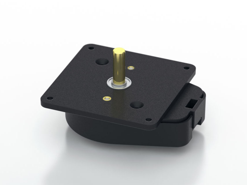
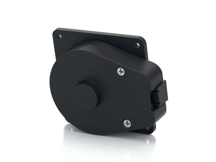
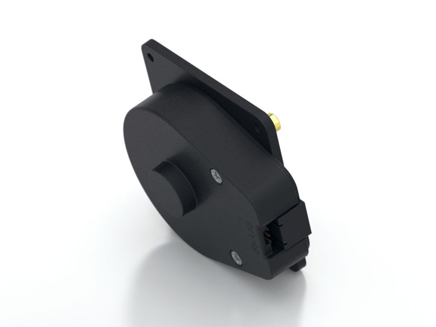
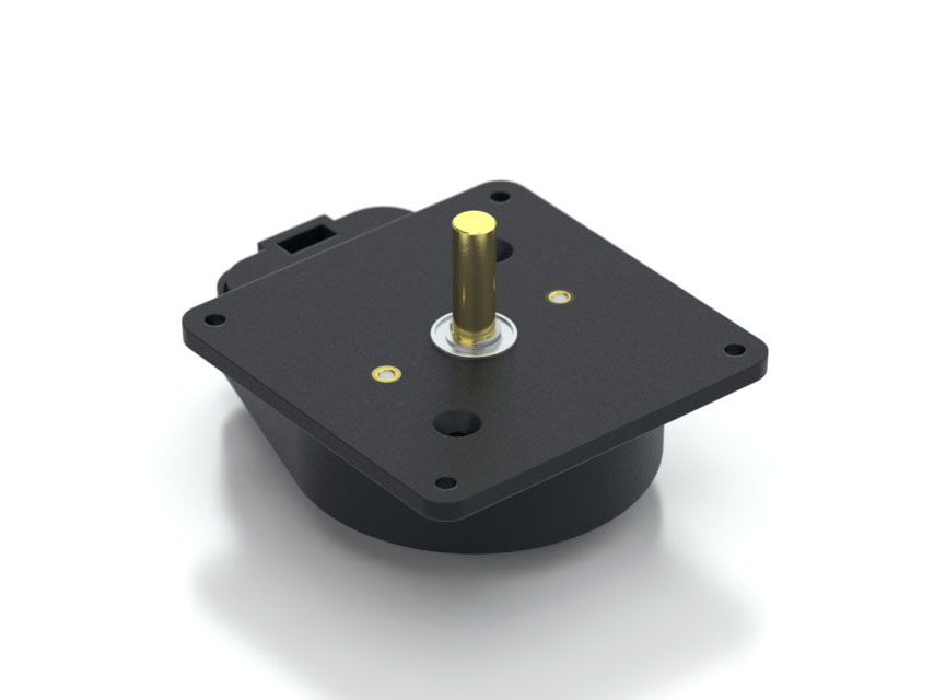
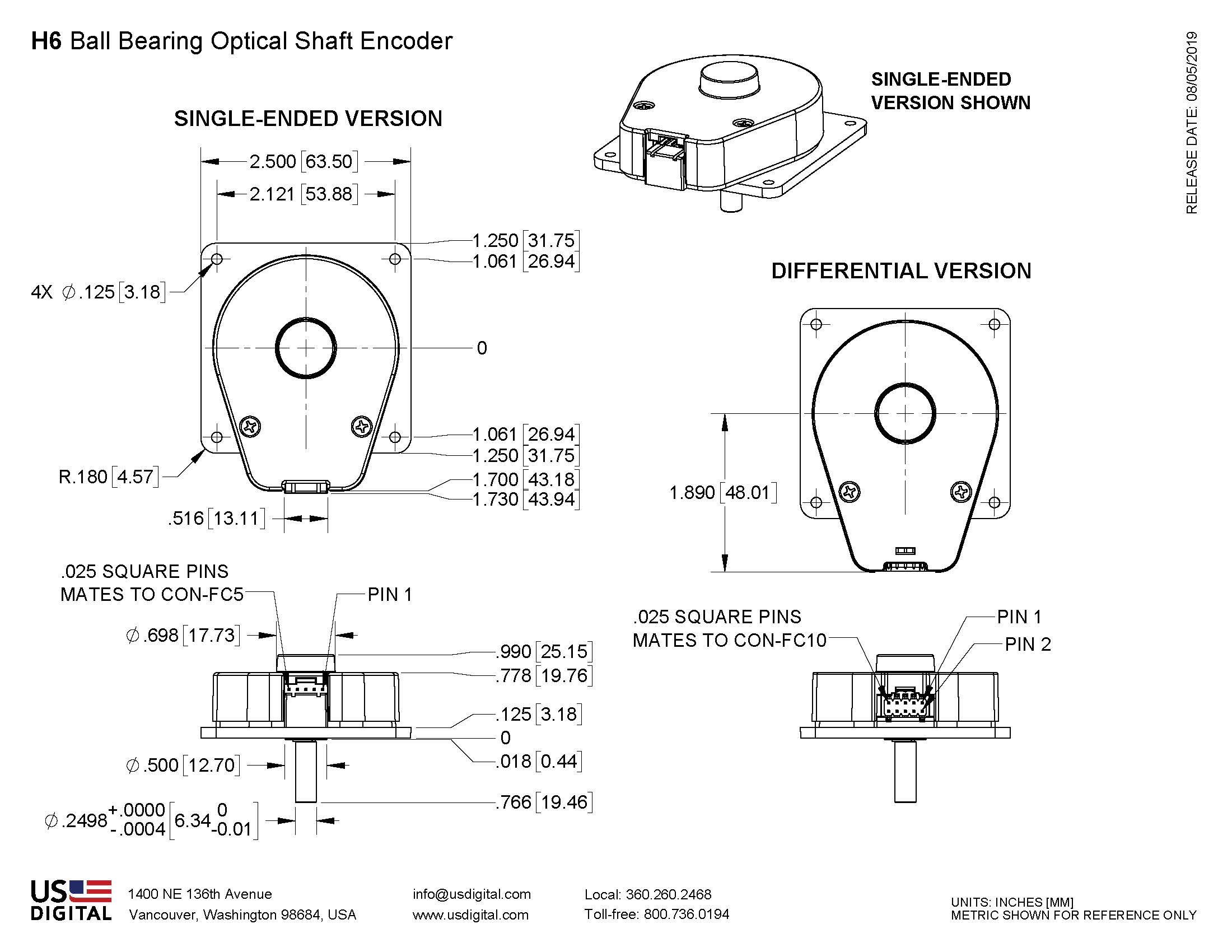
Please see the EM1 Component Change Notice.
1 / 4
  • H6
  • H6
  • H6
  • H6

Overview

  • Heavy duty ball bearings track up to 10,000 RPM
  • 2-channel quadrature, TTL squarewave outputs
  • Optional index (3rd channel)
  • Differential outputs available
  • Positive finger-latching connector
  • 64 to 2500 cycles per revolution (CPR)
  • 256 to 10000 pulses per revolution (PPR)
  • -40 to +100C operating temperature

The H6 series ball bearing optical shaft encoder has a molded polycarbonate housing,and utilizes either a 5-pin or 10-pin finger-latching connector. This non-contacting rotary to digital converter is...

Read more

Product Specifications

ParameterValueUnits
Operating Temperature -40 to 100 C
Vibration (5Hz to 2kHz) 20 G
Electrostatic Discharge, Human Body Model ± 4 kV
ParameterDimension / Units
Max. Acceleration 100000 rad/sec²
Max. Shaft Speed 10000 rpm
Max. Shaft Torque 0.05 in-oz
Max. Shaft Loading 2 lbs.
Bearing Life life in millions of revs. = (90/P)³
where P = radial load in pounds.
Weight
  Single-ended
  Differential

3.02 oz.
3.15 oz.
Max. Shaft Total Indicated Runout 0.006 in.
Moment of Inertia 0.001 oz-in-s²
Technical Bulletin TB1001 - Shaft and Bore Tolerances Download

B leads A for clockwise shaft rotation, and A leads B for counterclockwise rotation viewed from the shaft side of the encoder (see the EM1 page).

  • Specifications apply over entire operating temperature range.
  • Typical values are specified at Vcc = 5.0Vdc and 25°C.
  • For complete details, see the EM1 product page.
ParameterMin.Typ.Max.UnitsConditions
Supply Voltage 4.5  5.0 5.5 V  
Supply Current   27 33 mA CPR < 1000, no load 
  50 62 mA CPR ≥ 1000, no load
Low-level Output     0.5 V IOL = 8mA max.
High-level Output 2.0     V IOH = -8mA max.
4.2 4.8   V no load
Output Current Per Channel -8   8 mA
Output Rise Time   110   nS  
Output Fall Time   35   nS  
  • Specifications apply over entire operating temperature range.
  • Typical values are specified at Vcc = 5.0Vdc and 25°C.
  • For complete details, see the EM1 product pages.
ParameterMin.Typ.Max.UnitsConditions
Supply Voltage 4.5 5.0 5.5 V
Supply Current   29 36 mA CPR < 1000, no load 
  57 65 mA CPR ≥ 1000, no load
Low-level Output   0.2 0.4 V IOL = 20mA max.
High-level Output 2.4 3.4   V IOH = -20mA max.
Differential Output Rise/Fall Time     15  nS  
5-pin Single-ended10-pin Differential Standard
PinDescriptionPinDescription
1 Ground 1 Ground
2 Index 2 Ground
3 A channel 3 Index-
4 +5VDC power 4 Index+
5 B channel 5 A- channel
    6 A+ channel
    7 +5VDC power
    8 +5VDC power
    9 B- channel
    10 B+ channel
Title Date Description Download
EM1 LED Die - PCN 10162/7/2013As part of US Digital's continual assurance of supply strategy, we have qualified additional sources for our LED die used in our EM1 encoder module, which in turn impacts all of the following products:

EM1, E2, E3, E5, E6, H1, H15, H3, H5, H6, HB5M, HB6M, HD25, PE, S1, S2, S5, S6, T5 and T6

The device specification will remain the same, i.e. there will be no change to form, fit or function of the product(s) as specified by US Digital. The appropriate quality and reliability testing has been performed on representative products to ensure normal parametric distribution, consistent with US Digital's quality and reliability standards.
Download

Product Description

Restriction of Hazardous Substances

The H6 series ball bearing optical shaft encoder has a molded polycarbonate housing,and utilizes either a 5-pin or 10-pin finger-latching connector. This non-contacting rotary to digital converter is designed to provide digital feedback information. 

The H6 is fully assembled with a brass shaft, two 1/4" ID by 1/2" OD heavy duty ball bearings and a mounting plate.  The mounting plate comes with 2 mounting holes for screws #4 or smaller.

A secure connection to the H6 series encoder is made through a 5-pin (single-ended versions) or 10-pin (differential versions) finger-latching connector (sold separately). The mating connectors are available from US Digital with several cable options and lengths.

For differential versions: the internal differential line driver (26C31) can source and sink 20mA at TTL levels. The recommended receiver is industry standard 26C32. Maximum noise immunity is achieved when the differential receiver is terminated with a 150 Ω resistor in series with a .0047 μF capacitor placed across each differential pair. The capacitor simply conserves power; otherwise power consumption would increase by approximately 20mA per pair, or 60mA for 3 pairs.

Product Notes
  • Cables and connectors are not included and must be ordered separately.
  • US Digital warrants its products against defects in materials and workmanship for two years. See complete warranty for details.

Purchasing

Configure and Purchase

We recommend enabling Javascript when using the product configurator.

1. CPR
2. Index


3. Output


Product Part Number

This product requires configuration. Please supply the product options above.


Quantity Base Price
1 $112.50
5 $83.30
10 $72.35
50 $64.90
Over 50 Call for Quote
Quantity
Unit Price

$112.50

Subtotal

$112.50


For volume discounts, please use the above part number and contact us at:

sales@usdigital.com or

800.736.0194 (Toll Free)
360.260.2468 (Local)
Call US Digital.

Related Products & Accessories