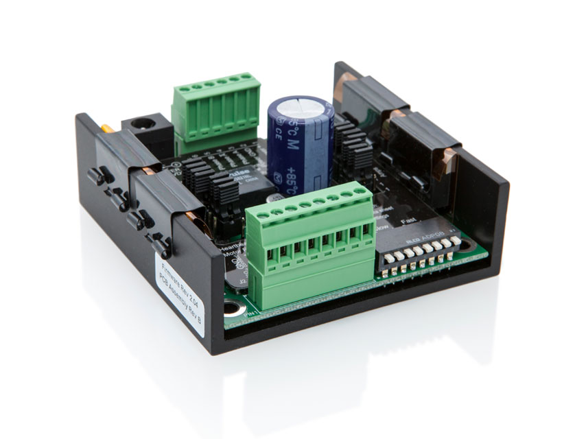
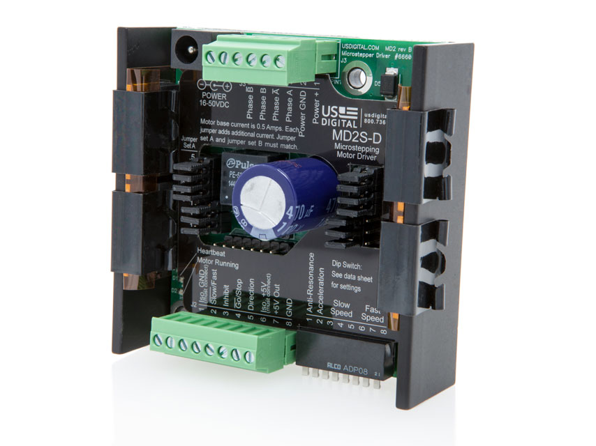
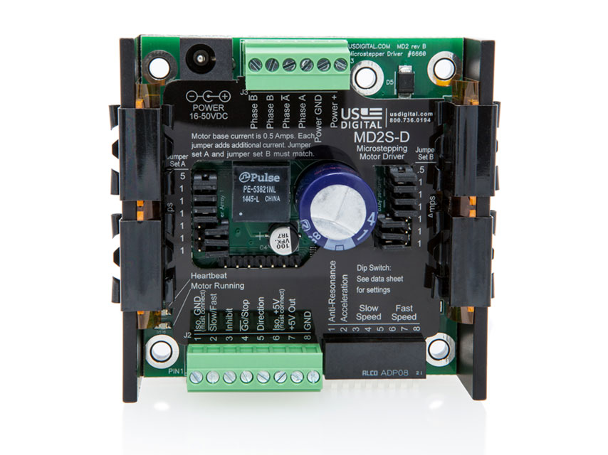
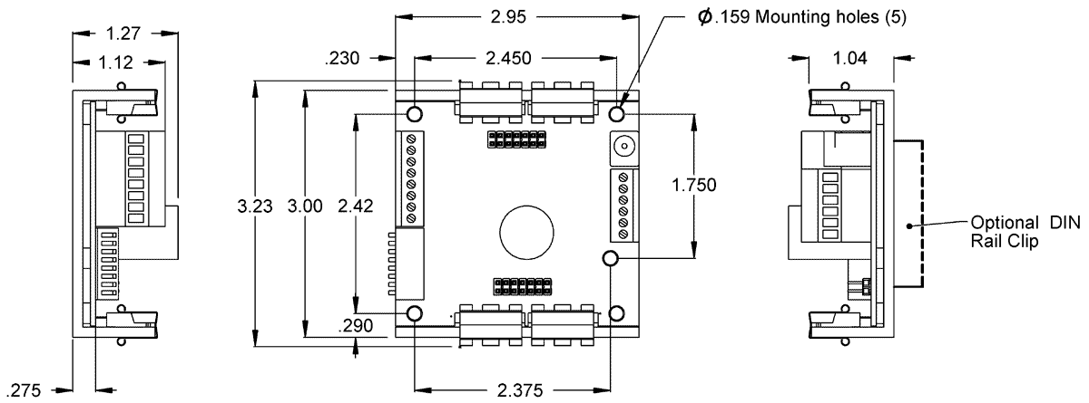
The 8 DIP switches may be changed while operating and changes take effect immediately without the need for a power-down cycle. The default position for all DIP switches is up. The speed or the direction of the MD2S-D can be changed on-the-fly by:
1) Changing the position of the speed select DIP switches.
2) Changing the Go / Stop input.
3) Changing the Slow / Fast input.
4) Changing the Direction input.
The MD2S-D will ramp to the new speed based on Fast / Slow acceleration determined by bit 2 of the DIP switch.
MD2S-P (Step / Direction Version) / MD2S-D (Digital Speed Control Version) DIP Switch Settings for SW1:
SWITCH 1 - ANTI-RESONANCE ENABLE
Up = Disable
Down = Enable
The stator of nearly all stepper motors have 50 magnetic teeth, 25 per winding, interleaved, and a permanent magnet rotor with matching alternating teeth. Applying current to the windings will generate attractive and repulsive forces to align the teeth of the stator and rotor. A four step quadrature sequence that applies full current in alternating polarities to each winding will step the motor through 1/50 of a revolution, resulting in 200 full steps per revolution. Switching the magnetic field in full steps from one extreme to the other causes the rotor to jerk, producing obvious noise and vibration. The rotor will ring by alternately leading, then lagging the commanded angle. The resonance frequency is dependent on the size and weight of the rotor. When full stepping, the resonance of a stepper motor is so pronounced that the motor will commonly stall even when no load is present.
Microstepping executes the same sequence but in smaller increments (sine and cosine) and solves the primary resonance problem. The finer the increments (resolution), the smoother, quieter and finer the movements. This same low frequency resonance can still be excited and will progressively build when spinning at higher speeds or when microsteps occur at frequencies related to the resonant frequency (typically around 210 Hz). It sounds like low frequency growling. The MD2S can sense and cancel this resonance to maintain smooth quiet high speed torque when enabled by DIP switch 1.
MD2S-P (Step / Direction Version) / DIP Switch Settings for SW2 to SW8:
SWITCH 2 -
Up = Step on Falling Edge
Down = Step on Rising Edge
SWITCH 3 - ZERO SPEED CURRENT REDUCTION
Up = Disable
Down = Enable
When enabled, the MD2S will automatically reduce motor current by 50% when step pulses have not occurred for at least one second. This will save power and allow the motor to cool between moves.
The motor position may change slightly when current reduction kicks in. Therefore, the current reduction feature should be disabled if the resting position of the motor must be accurately maintained. If this current reduction kicks in, the MD2S will turn on the red LED. Asserting J2 pin-2 (Reduce Current input) has priority and is not additive.
SWITCHES 8 TO 4 - RESOLUTION
These 5 DIP switches are used to select one of 31 microstepping resolutions from 2 to 256 microsteps per step. See the resolution table for a map. The higher the resolution, the smoother and quieter the motor. Special resolutions may be available upon request. See below for Microstep Resolution Table.
Decimal
Code |
Hex
Code |
Microsteps
per Step |
Microsteps
per Rev. |
16
SW4 |
8
SW5 |
4
SW6 |
2
SW7 |
1
SW8 |
| 29 |
1D |
2* |
400 |
↑ |
↑ |
↑ |
↓ |
↑ |
| 30 |
1E |
4* |
800 |
↑ |
↑ |
↑ |
↑ |
↓ |
| 0 |
00 |
5 |
1000 |
↓ |
↓ |
↓ |
↓ |
↓ |
| 1 |
01 |
6 |
1200 |
↓ |
↓ |
↓ |
↓ |
↑ |
| 2 |
02 |
8 |
1600 |
↓ |
↓ |
↓ |
↑ |
↓ |
| 3 |
03 |
9 |
1800 |
↓ |
↓ |
↓ |
↑ |
↑ |
| 4 |
04 |
10 |
2000 |
↓ |
↓ |
↑ |
↓ |
↓ |
| 5 |
05 |
12 |
2400 |
↓ |
↓ |
↑ |
↓ |
↑ |
| 6 |
06 |
15 |
3000 |
↓ |
↓ |
↑ |
↑ |
↓ |
| 7 |
07 |
16 |
3200 |
↓ |
↓ |
↑ |
↑ |
↑ |
| 8 |
08 |
18 |
3600 |
↓ |
↑ |
↓ |
↓ |
↓ |
| 9 |
09 |
20 |
4000 |
↓ |
↑ |
↓ |
↓ |
↑ |
| 10 |
0A |
24 |
4800 |
↓ |
↑ |
↓ |
↑ |
↓ |
| 11 |
0B |
25 |
5000 |
↓ |
↑ |
↓ |
↑ |
↑ |
| 12 |
0C |
30 |
6000 |
↓ |
↑ |
↑ |
↓ |
↓ |
| 13 |
0D |
32 |
6400 |
↓ |
↑ |
↑ |
↓ |
↑ |
| 14 |
0E |
36 |
7200 |
↓ |
↑ |
↑ |
↑ |
↓ |
| 15 |
0F |
40 |
8000 |
↓ |
↑ |
↑ |
↑ |
↑ |
| 16 |
10 |
48 |
9600 |
↑ |
↓ |
↓ |
↓ |
↓ |
| 17 |
11 |
50 |
10000 |
↑ |
↓ |
↓ |
↓ |
↑ |
| 18 |
12 |
60 |
12000 |
↑ |
↓ |
↓ |
↑ |
↓ |
| 19 |
13 |
64 |
12800 |
↑ |
↓ |
↓ |
↑ |
↑ |
| 20 |
14 |
80 |
16000 |
↑ |
↓ |
↑ |
↓ |
↓ |
| 21 |
15 |
100 |
20000 |
↑ |
↓ |
↑ |
↓ |
↑ |
| 22 |
16 |
120 |
24000 |
↑ |
↓ |
↑ |
↑ |
↓ |
| 23 |
17 |
125 |
25000 |
↑ |
↓ |
↑ |
↑ |
↑ |
| 24 |
18 |
128 |
25600 |
↑ |
↑ |
↓ |
↓ |
↓ |
| 25 |
19 |
200 |
40000 |
↑ |
↑ |
↓ |
↓ |
↑ |
| 26 |
1A |
240 |
48000 |
↑ |
↑ |
↓ |
↑ |
↓ |
| 27 |
1B |
250 |
50000 |
↑ |
↑ |
↓ |
↑ |
↑ |
| 28 |
1C |
256 |
51200 |
↑ |
↑ |
↑ |
↓ |
↓ |
| 29 |
1D |
2* |
400 |
↑ |
↑ |
↑ |
↓ |
↑ |
| 30 |
1E |
4* |
800 |
↑ |
↑ |
↑ |
↑ |
↓ |
| 31 |
1F |
256 |
51200 |
↑ |
↑ |
↑ |
↑ |
↑ |
*These resolutions are available with firmware revision 2.05 or later.
Please note: Special resolutions may be available upon request.
MD2S-D (Digital Speed Control Version) / DIP Switch Settings for SW2 to SW8:
SWITCH 2 -
Up = Enable Fast Acceleration
Down = Disable Fast Acceleration
Fast acceleration is factory set to 250 milliseconds per 1000 RPM. Slow acceleration is factory set to 500 milliseconds per 1000 RPM. The acceleration may also be customer specified.
SWITCHES 3, 4 & 5 - SLOW SPEEDS
These 3 switches are used to select one of 8 slow speeds. When J2 pin 2 is pulled low, the motor will ramp to the speed selected by these 3 switches. The standard speed choices are shown in the table below. These switches may be switched at any time. The MD2S will ramp up or down to follow the real-time setting of the switches. Other speed choices may be customer specified upon request by contacting a US Digital application engineer.
| Code |
RPM |
RPS |
2
SW3 |
1
SW4 |
0
SW5 |
| 0 |
4 |
0.07 |
↓ |
↓ |
↓ |
| 1 |
10 |
0.17 |
↓ |
↓ |
↑ |
| 2 |
25 |
0.42 |
↓ |
↑ |
↓ |
| 3 |
50 |
0.83 |
↓ |
↑ |
↑ |
| 4 |
100 |
1.67 |
↑ |
↓ |
↓ |
| 5 |
200 |
3.33 |
↑ |
↓ |
↑ |
| 6 |
300 |
5.00 |
↑ |
↑ |
↓ |
| 7 |
360 |
6.00 |
↑ |
↑ |
↑ |
SWITCHES 6, 7 & 8 - FAST SPEEDS
These 3 switches are used to select one of 8 fast speeds. When J2 pin 2 is high, the motor will ramp to the speed selected by these 3 switches. The standard speed choices are shown in the table below. These switches may be switched at any time. The MD2S will ramp up or down to follow the real-time setting of the switches. Other speed choices may be customer specified upon request by contacting a US Digital application engineer.
| Code |
RPM |
RPS |
2
SW6 |
1
SW7 |
0
SW8 |
| 0 |
480 |
8 |
↓ |
↓ |
↓ |
| 1 |
600 |
10 |
↓ |
↓ |
↑ |
| 2 |
720 |
12 |
↓ |
↑ |
↓ |
| 3 |
900 |
15 |
↓ |
↑ |
↑ |
| 4 |
1200 |
20 |
↑ |
↓ |
↓ |
| 5 |
1500 |
25 |
↑ |
↓ |
↑ |
| 6 |
1800 |
30 |
↑ |
↑ |
↓ |
| 7 |
2100 |
35 |
↑ |
↑ |
↑ |
