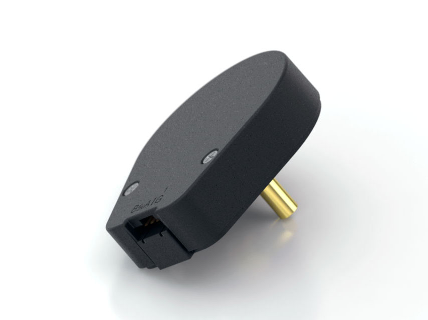
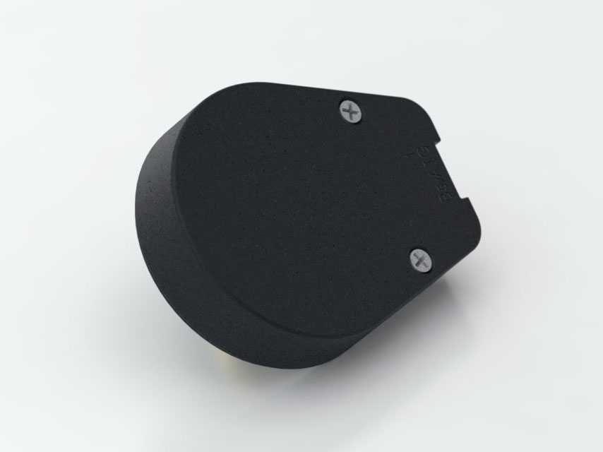
S6 Product Description

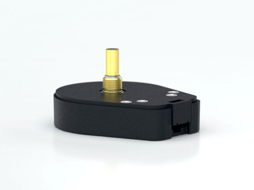
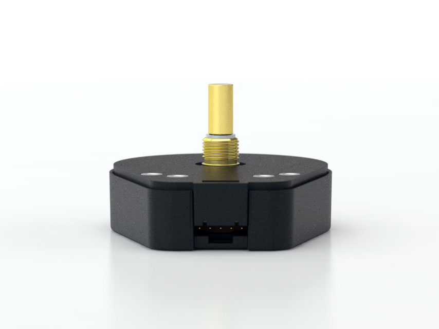
The S6 series high resolution optical shaft encoder is a non-contacting rotary to digital converter. Useful for position feedback or manual interface, the encoder converts real-time shaft angle, speed, and direction into TTL-compatible quadrature outputs with or without index. It operates from a single +5VDC supply.
Three shaft torque versions are available:
- The default torque version has a sleeve bushing designed to provide torque and feel ideal for front panel human interface applications.
- The ball-bearing version uses miniature precision ball bearings that are suitable for high-speed and ultra-low torque applications.
- The light static drag option has a sleeve bushing that does not intentionally add torque for low RPM applications where a small amount of torque is acceptable.
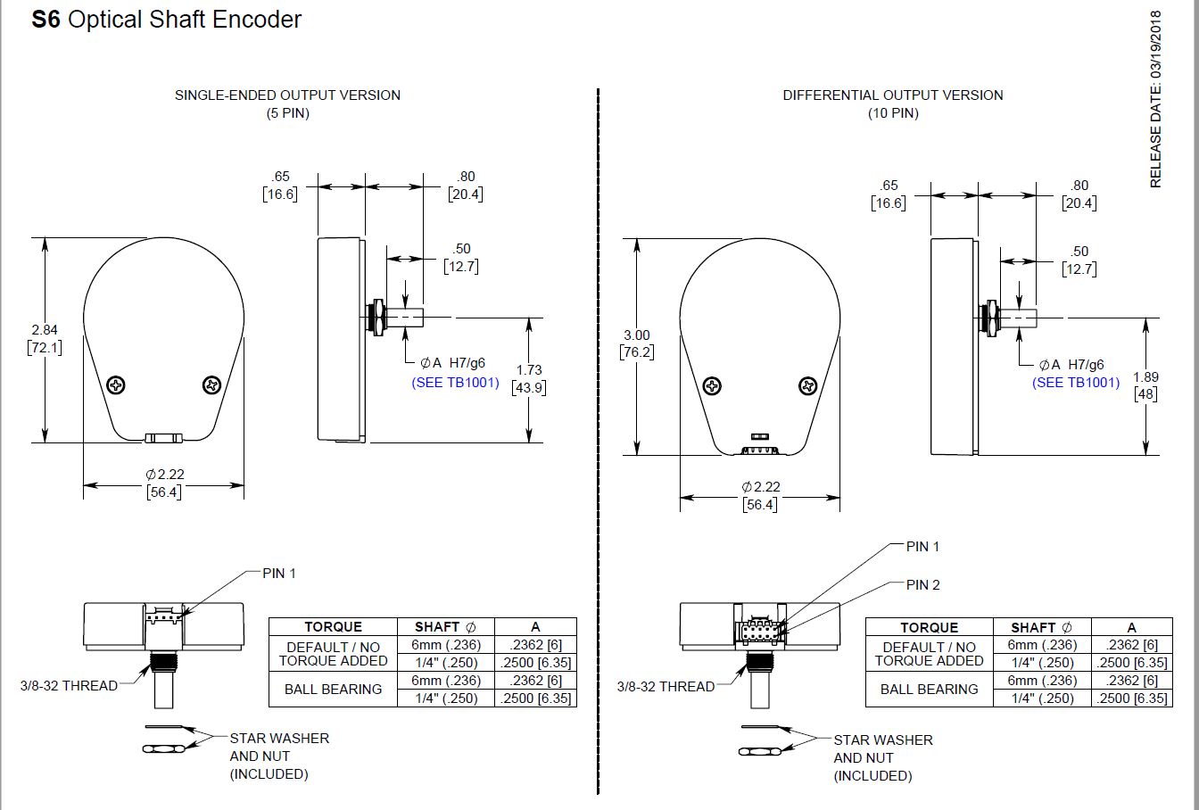
A secure connection to the S6 Series encoder is made through a 5-pin (single-ended versions) or 10-pin (differential or high-voltage versions) latching connector. The mating connectors are available from US Digital with several cable options and lengths.
The internal differential line driver (26C31) can source and sink 20mA at TTL levels for differential versions. The recommended receiver is the industry-standard 26C32. Maximum noise immunity is achieved when the differential receiver is terminated with a 150Ω resistor in series with a .0047 μF capacitor placed across each differential pair. The capacitor conserves power; otherwise, power consumption would increase by approximately 20mA per pair or 60mA for three pairs.
Product Specifications
View here or download the specifications
ENVIRONMENTAL
| Parameter |
Value |
Units |
| Operating Temperature, CPR < 2000 |
-40 to 100 |
C |
| Operating Temperature, CPR ≥ 2000 |
-25 to 100 |
C |
Electrostatic Discharge
Single-ended (S option), IEC 61000-4-2
Differential (D, L option), Human Body Model
High-Voltage, Open-collector (H, C option), IEC 61000-4-2 |
± 4
± 2
± 4 |
kV |
| Vibration (10Hz to 2kHz, sinusoidal) |
20 |
G |
| Shock (6 milliseconds, half-sine) |
75 |
G |
MECHANICAL
| PARAMETER |
SLEEVE BUSHING |
BALL BEARING |
| Max. Acceleration |
250000 rad/sec² |
250000 rad/sec² |
| Max. Shaft Speed (mechanical) |
100 rpm (1) |
10000 rpm (1) |
| Max. Shaft Torque |
0.5 ± 0.2 in-oz
0.3 in-oz (N-option) |
0.05 in-oz |
| Max. Shaft Loading |
2 lbs. dynamic
20 lbs. static |
1 lb. |
| Bearing Life |
> 1000000 revolutions |
L10 = (19.3/Fr)³ *
Where L10 = bearing life in millions of revs, and
Fr = radial shaft loading in pounds |
Weight
Single-ended (S option)
Differential (D option)
High-Voltage, Open-Collector (H, C option) |
1.92 oz.
2.00 oz.
2.00 oz. |
1.78 oz.
1.86 oz.
1.86 oz. |
| Max. Shaft Runout |
0.0015 in. T.I.R. |
0.0015 in. T.I.R. |
| Max. Panel Nut Tightening Torque |
20 in-lbs |
20 in-lbs |
| Technical Bulletin TB1001 - Shaft and Bore Tolerances |
Download |
* Only valid with negligible axial shaft loading.
(1) The maximum speed due to electrical considerations is dependent on the CPR. See the EM1 and EM2 product pages.
PHASE RELATIONSHIP
B leads A for clockwise shaft rotation, and A leads B for counterclockwise rotation when viewed from the shaft side of the encoder.
SINGLE-ENDED OPTION
- S option provides 5V TTL compatible outputs
- Specifications apply over the entire operating temperature range
- Typical values are specified at Vcc = 5.0Vdc and 25°C
- For complete details, see the EM1 and EM2 product pages
| PARAMETER |
MIN. |
TYP. |
MAX. |
UNITS |
CONDITIONS |
| Supply Voltage |
4.5 |
5.0 |
5.5 |
V |
|
| Supply Current |
|
27 |
33 |
mA |
CPR < 1000, no load |
| |
54 |
62 |
mA |
CPR ≥ 1000 and < 3600, no load |
| |
72 |
85 |
mA |
CPR ≥ 3600, no load |
| Low-level Output |
|
|
0.5 |
V |
IOL = 8mA max., CPR < 3600 |
| |
|
0.5 |
mA |
IOL = 5mA max., CPR ≥ 3600 |
| |
0.05 |
|
mA |
no load, CPR < 3600 |
| |
0.25 |
|
mA |
no load, CPR ≥ 3600 |
| High-level Output |
2.0 |
|
|
V |
IOH = -8mA max., CPR < 3600 |
| 2.0 |
|
|
V |
IOH = -5mA max., CPR ≥ 3600 |
| |
4.8 |
|
V |
no load, CPR < 3600 |
| |
3.5 |
|
V |
no load, CPR ≥ 3600 |
| Output Current Per Channel |
-8 |
|
8 |
mA |
CPR < 3600 |
| -5 |
|
5 |
mA |
CPR ≥ 3600 |
| Output Rise Time |
|
110 |
|
nS |
CPR < 3600 |
| |
50 |
|
nS |
CPR ≥ 3600 |
| Output Fall Time |
|
35 |
|
nS |
CPR < 3600 |
| |
50 |
|
nS |
CPR ≥ 3600 |
DIFFERENTIAL OPTION
- D Option provides differential line driver outputs
- Specifications apply over the entire operating temperature range
- Typical values are specified at Vcc = 5.0Vdc and 25°C
- For complete details, see the EM1 and EM2 product pages
| PARAMETER |
MIN. |
TYP. |
MAX. |
UNITS |
CONDITIONS |
| Supply Voltage |
4.5 |
5.0 |
5.5 |
V |
| Supply Current |
|
29 |
36 |
mA |
CPR < 1000, no load |
| |
56 |
65 |
mA |
CPR ≥ 1000 and < 3600, no load |
| |
74 |
88 |
mA |
CPR ≥ 3600, no load |
| Low-level Output |
|
0.2 |
0.4 |
V |
IOL = 20mA max. |
| High-level Output |
2.4 |
3.4 |
|
V |
IOH = -20mA max. |
| Differential Output Rise/Fall Time |
|
|
15 |
nS |
|
HIGH-VOLTAGE OPTION
- H option uses a higher supply voltage and provides both single-ended and open-collector outputs
- Single-ended outputs are 5V TTL compatible (same as S option)
- Specifications apply over the entire operating temperature range
- For complete details, see the EM1 or EM2 product pages
| PARAMETER |
MIN. |
TYP. |
MAX. |
UNITS |
CONDITIONS |
| Supply Voltage |
7.5 |
|
30.0 |
V |
|
| Supply Current, 24V power |
|
8 |
10 |
mA |
CPR < 500, no load |
| |
16 |
19 |
mA |
CPR ≥ 500 and < 2000, no load |
| |
22 |
25 |
mA |
CPR ≥ 2000, no load |
| Open Collector "On" Resistance |
|
2 |
|
ohms |
|
| Open Collector Sink Current |
|
|
200 |
mA |
|
| Output Low Voltage |
|
|
0.4 |
V |
200 mA sink current |
| Open Collector Pullup Voltage |
|
|
50 |
V |
|
PIN-OUTS
|
5-PIN SINGLE-ENDED
S OPTION (1)
|
10-PIN DIFFERENTIAL
D OPTION (2) |
| Pin |
Description |
Pin |
Description |
| 1 |
Ground |
1 |
Ground |
| 2 |
Index |
2 |
Ground |
| 3 |
A channel |
3 |
Index- |
| 4 |
+5VDC power |
4 |
Index+ |
| 5 |
B channel |
5 |
A- channel |
| |
|
6 |
A+ channel |
| |
|
7 |
+5VDC power |
| |
|
8 |
+5VDC power |
| |
|
9 |
B- channel |
| |
|
10 |
B+ channel |
10-PIN HIGH-VOLTAGE
H OPTION (2) |
| Pin |
Description |
| 1 |
Ground |
| 2 |
Ground |
| 3 |
Index- (open collector) |
| 4 |
Index+ (single-ended) |
| 5 |
A- channel (open collector) |
| 6 |
A+ channel (single-ended) |
| 7 |
7.5-30V power |
| 8 |
7.5-30V power |
| 9 |
B- channel (open collector) |
| 10 |
B+ channel (single-ended) |
(1) 5-pin single-ended mating connector is CON-FC5.
(2) 10-pin differential mating connector is CON-FC10.
PRODUCT CHANGE NOTIFICATIONS
| Title |
Date |
Description |
Download |
| Marketing/Insert - PCN 7058 |
11/04/2020 |
As part of our ongoing continuous improvement efforts, improvements are being incorporated into the E6, S6 and H6 series of Optical Encoders, including both single-end and differential output versions. |
Download |
| Laser Marking - PCN 5253 |
6/17/2015 |
As part of our ongoing continuous improvement efforts, US Digital is changing the labeling/marking method for our E3, E6, H3, H6, S1, S2 and S6 products. |
Download |
| EM1 & EM2 Update - PCN 4199 |
1/14/2014 |
Based on our continuous process improvement program, US Digital is changing the current marking method for our EM1 and EM2 encoder modules to a serialization method. This change will allow for each module to have a unique code; the current marking method is based on a date code system that includes all encoder modules produced within a specific week / year. The serialization system will be based on a hexadecimal system. |
Download |
| EM1 LED Die - PCN 1016 |
2/7/2013 |
As part of US Digital's continual assurance of supply strategy, we have qualified additional sources for our LED die used in our EM1 encoder module, which in turn impacts all of the following products:
EM1, E2, E3, E5, E6, H1, H15, H3, H5, H6, HB5M, HB6M, HD25, PE, S1, S2, S5, S6, T5 and T6
The device specification will remain the same, i.e. there will be no change to form, fit or function of the product(s) as specified by US Digital. The appropriate quality and reliability testing has been performed on representative products to ensure normal parametric distribution, consistent with US Digital's quality and reliability standards. |
Download |
Additional Information
Product Notes
-
Cables and connectors are not included and must be ordered separately.
-
For ordering information please see the Compatible Cables / Connectors section above.
-
US Digital® warrants its products against defects in materials and workmanship for two years. See complete warranty for details.
-
For ordering information please configure the product and you'll see the Compatible Cables / Connectors section above.
Datasheets
User Guides
Related
3D Model Downloads
Please
configure your product first
to download a 3D model.
(Note: The formats below will become links if there are 3D models available.)
-
SolidWorks Format
-
IGES Format
-
Parasolid Format
-
STEP Format
Product Configurator
Our products are not currently available for direct online purchase. To place an order please contact us directly with your part number.
For purchasing or volume discounts, please configure the part above, then use the completed part number and contact us!
Feedback
US Digital's mission is a commitment to quality and constant improvement. If you find an error to a product on this page, please let us know!