PE Features
- Standard 3/8 in. diameter mounting stem
- Compact design
- Linear ranges from 1 in. to 2 in.
- 120 CPI to 2,000 CPI
- 0.0005 in. to 0.0021 in. resolution
- latching connector
- A and B quadrature digital output
- Optional 3rd channel (index)
- TTL compatible outputs
- Interfaces with all US Digital® support products
The PE is no longer available for purchase.
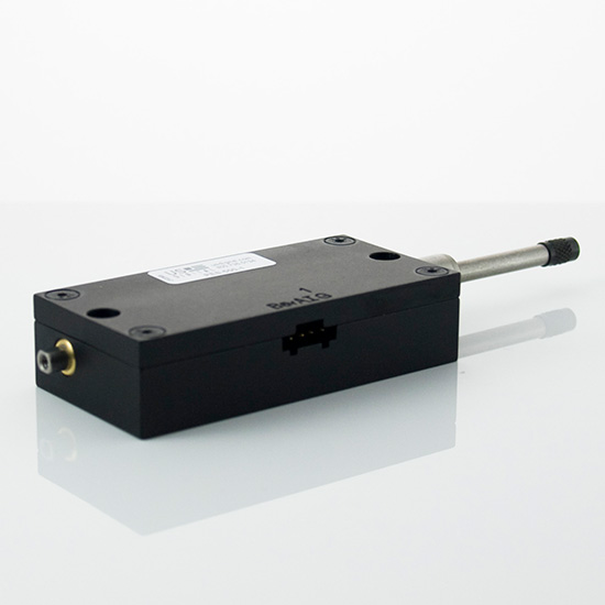
PE Product Description
The PE series linear plunger-style optical encoder has a machined aluminum enclosure. The PE provides either single-ended or differential quadrature encoder output in a convenient mechanical package. Various CPI (counts per inch) ranging from 120 CPI to 2000 CPI are available. Using x4 quadrature counting, the available resolutions range from 0.00013 in. to 0.0021 in. Note that 127 CPI gives a resolution of 50 micrometers.
The PE features smooth linear bearings for repeatable measurements and an internal spring to return the plunger to its fully extended position. Standard linear measurement ranges are from 1 to 2 inches. The precision plunger has #4-48 threads on both ends to accept industry-standard contact points. The PE may be mounted four different ways: the #4-40 clearance body through holes, the #4-40 tapped blind holes, the standard 3/8 in. diameter mounting stem, or the lug back option.
The single-ended output interface is normally designed for applications of 10 feet or less. For longer cable lengths, the differential output interface is recommended.
The internal encoder module incorporates a lensed LED light source and a monolithic photodetector array. The monolithic photodetector has signal shaping electronics that produce a two-channel quadrature with optional index bounceless TTL output. When Index is specified, the default location is in the middle of the linear probe's range of travel with a location tolerance of ±0.050 in.
For differential versions: the internal differential line driver (26C31) can source and sink 20mA at TTL levels. The recommended receiver is industry standard 26C32. Maximum noise immunity is achieved when the differential receiver is terminated with a 150 Ω resistor in series with a .0047 μF capacitor placed across each differential pair. The capacitor simply conserves power; otherwise, power consumption would increase by approximately 20 mA per pair or 40 mA for 2 pairs.
A secure connection to the PE encoder is made through a 5-pin (single-ended versions) or 10-pin (differential versions) polarized connector (sold separately). The mating connectors are available from US Digital with several cable options and lengths.
Mechanical Drawings
Specifications
ENVIRONMENTAL
The PE performs best over a 0 C to 50 C temperature range due to a fairly linear temperature coefficient. They will however, operate at temperatures above 50C, but the thermal temperature coefficient becomes non linear at elevated temperatures. The negative temperature coefficient indicates the actual measured distance will decrease slightly with temperature increase.
| PARAMETER | SPECIFICATION |
|---|---|
| Recommended Operating Temperature | 0 C to 50 C |
| 1" Product Temperature Coefficient | -0.000036 in/C |
| 2" Product Temperature Coefficient | -0.000075 in/C |
| Operating Temperature, CPI < 1000 | -40 to 100 C |
| Operating Temperature, CPI ≥ 1000 | -25 to 100 C |
| Vibration (5 Hz to 2000 Hz) | 20 G |
| Electrostatic Discharge | ± 4 kV Human Body Model |
MECHANICAL
| PARAMETER | DIMENSION | UNITS |
|---|---|---|
| Plunger Force (1" version) | 3 to 6 typical | oz. |
| Plunger Force (2" version) | 3 to 9 typical | oz. |
| Travel (1" version) | 1.050 min. | in. |
| Travel (2" version) | 2.050 min. | in. |
| Side Load | 1 | lb. |
- When Index is specified, the default location is in the middle of the linear probe's range of travel with a location tolerance of ±0.050".
TRACKING SPEED
The maximum tracking speed of the encoder can be calculated as follows:
Maximum tracking speed ( in. / sec.) = 300000/CPI. Where CPI is the counts-per-inch of the encoder.
The tracking speed for several common CPI's are shown in the table below.
| PARAMETER | MAX. | UNITS |
|---|---|---|
| Tracking Speed, 125 CPI | 800 | in/sec |
| Tracking Speed, 127 CPI | 787 | in/sec |
| Tracking Speed, 250 CPI | 400 | in/sec |
| Tracking Speed, 500 CPI | 200 | in/sec |
| Tracking Speed, 1000 CPI | 360 | in/sec |
| Tracking Speed, 2000 CPI | 360 | in/sec |
RESOLUTIONS
The position resolution in inches using x4 quadrature counting (count every transition of the A and B outputs) can be calculated as follows:
Resolution = 1/(4*CPI) where CPI is the counts-per-inch of the encoder. Several common values are shown in the table below.
| CPI | RESOLUTION |
|---|---|
| 125 | 0.002 in. |
| 127 | 50.0 μm |
| 250 | 0.0010 in. |
| 500 | 0.0005 in. |
| 1000 | 0.00025 in. |
| 2000 | 0.000125 in. |
Other resolutions may be available upon request.
SINGLE-ENDED ELECTRICAL
- Specifications apply over entire operating temperature range.
- Typical values are specified at Vcc = 5.0Vdc and 25°C.
- For complete details, see the EM1 or EM2 product pages.
| PARAMETER | MIN. | TYP. | MAX. | UNITS | CONDITIONS |
|---|---|---|---|---|---|
| Supply Voltage | 4.5 | 5.0 | 5.5 | V | |
| Supply Current | 27 | 33 | mA | CPI < 300, no load | |
| 55 | 62 | mA | CPI ≥ 300, no load | ||
| Low-level Output | 0.5 | V | IOL = 8mA max. | ||
| High-level Output | 2.0 | V | IOH = -8mA max. | ||
| 4.2 | 4.8 | V | no load | ||
| Output Current Per Channel | -8 | 8 | mA | ||
| Output Rise Time | 110 | nS | |||
| Output Fall Time | 35 | nS |
DIFFERENTIAL ELECTRICAL
- Specifications apply over entire operating temperature range.
- Typical values are specified at Vcc = 5.0Vdc and 25°C.
- For complete details, see the EM1 product page.
| PARAMETER | MIN. | TYP. | MAX. | UNITS | CONDITIONS |
|---|---|---|---|---|---|
| Supply Voltage | 4.5 | 5.0 | 5.5 | V | |
| Supply Current | 29 | 36 | mA | CPI < 300, no load | |
| 57 | 65 | mA | CPI ≥ 300, no load | ||
| Low-level Output | 0.2 | 0.4 | V | IOL = 20mA max. | |
| High-level Output | 2.4 | 3.4 | V | IOH = -20mA max. | |
| Differential Output Rise/Fall Time | 15 | nS |
PIN-OUT
5-PIN SINGLE-ENDED:
| PIN | DESCRIPTION |
|---|---|
| 1 | Ground |
| 2 | Index |
| 3 | A channel |
| 4 | +5VDC power |
| 5 | B channel |
10-PIN DIFFERENTIAL:
| PIN | DESCRIPTION |
|---|---|
| 1 | Ground |
| 2 | Ground |
| 3 | Index- |
| 4 | Index+ |
| 5 | A- channel |
| 6 | A+ channel |
| 7 | +5VDC power |
| 8 | +5VDC power |
| 9 | B- channel |
| 10 | B+ channel |
ACCESSORIES
1. For tapped blind hole mounting:
Part #: SCREW-440-250-PH
Description: #4-40 x 1/4"
Quantity Required for Mounting: 4 per encoder
Part #: SCREW-440-375-PH
Description: #4-40 x 3/8"
Quantity Required for Mounting: 4 per encoder
Part #: SCREW-440-500-PH
Description: #4-40 x 1/2"
Quantity Required for Mounting: 4 per encoder
Part #: SCREW-440-625-PH
Description: #4-40 x 5/8"
Quantity Required for Mounting: 4 per encoder
2. For body through hole mounting:
Part #: SCREW-440-1000-PH
Description: #4-40 x 1"
Quantity Required for Mounting: 2 per encoder
Notes
- Cables and connectors are not included and must be ordered separately.
- For ordering information please see the Compatible Cables / Connectors section above.
- US Digital® warrants its products against defects in materials and workmanship for two years. See complete warranty for details.
Configuration Options |
| PE |
|
PLEASE NOTE: This chart is for informational use only. Certain product configuration combinations are not available. Visit the PE product page for pricing and additional information. |