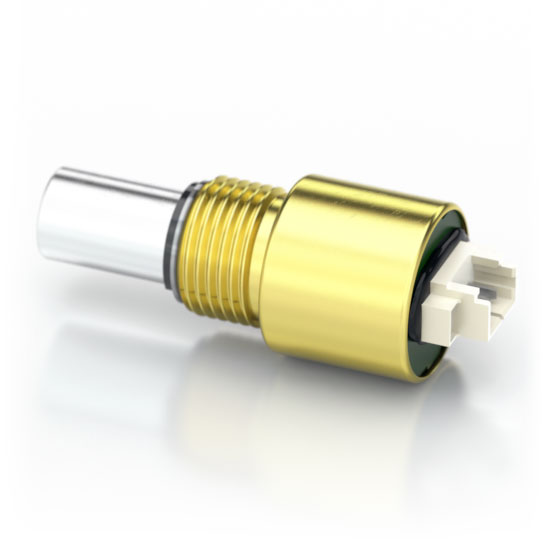
MA3 Features
- Miniature size (0.48 in. diameter)
- Non-contacting magnetic single chip sensing technology
- -40C to 125C operating temperature range
- 10-bit Analog output - 2.6 kHz sampling rate
- 10-bit PWM output - 1,024 positions per revolution, 1 kHz
- 12-bit PWM output - 4,096 positions per revolution, 250 Hz
MA3 Product Description
The MA3 is a miniature rotary absolute shaft encoder that reports the shaft position over 360° with no stops or gaps. The MA3 is available with an analog or a pulse width modulated (PWM) digital output.
Analog output provides an analog voltage that is proportional to the absolute shaft position. Analog output is only available in 10-bit resolution.
PWM output provides a pulse duty cycle that is proportional to the absolute shaft position. PWM output is available in 10-bit and 12-bit resolutions. While the accuracy is the same for both encoders, the 12-bit version provides a higher resolution.
Three shaft torque options are available:
- Default (-D): sleeve bushing with higher damping for human interface applications.
- Ball bearing (-B): miniature precision ball bearings suitable for high-speed applications (1/8" diameter shaft only).
- Light static drag (-N): sleeve bushing with lower damping for low-speed applications.
Connecting to the MA3 is simple. The 3-pin high retention snap-in 1.25mm pitch polarized connector provides for +5V, output, and ground.
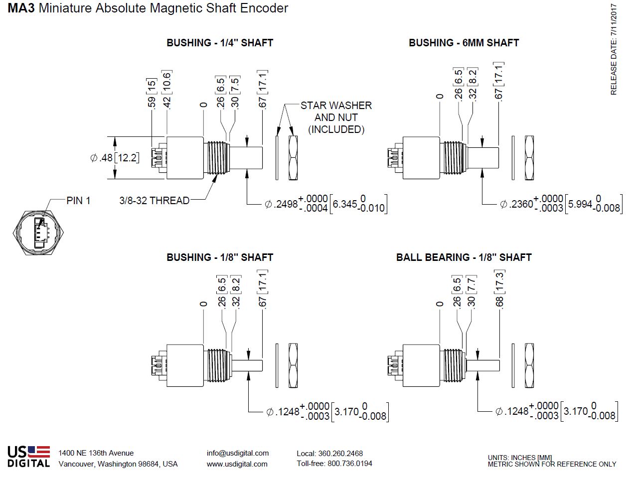
Mechanical Drawings
Specifications
ENVIRONMENTAL
| PARAMETER | VALUE | UNITS |
|---|---|---|
| Operating Temperature | -40 to +125 | C |
| Vibration (5Hz to 2kHz) | 20 | G |
| Electrostatic Discharge, Human Body Model MIL-STD-883E, Method 3015.7 |
± 2 | kV |
MECHANICAL
| SPECIFICATION | SLEEVE BUSHING | BALL BEARING |
|---|---|---|
| Moment of Inertia | 4.1 x 10^-6 oz-in-s² | 4.1 x 10^-6 oz-in-s² |
| Max. Shaft Speed (1) (mechanical) |
100 RPM | 15000 RPM |
| Max. Acceleration | 10000 rad/sec² | 250000 rad/sec² |
| Max. Shaft Torque | 0.5 in-oz (D-option) 0.3 in-oz (N-option) |
0.05 in-oz (B-option) |
| Max. Shaft Loading | 2 lb. dynamic 20 lb. static |
1 lb. |
| Bearing Life (2) | > 1,000,000 revolutions | L10 = (18.3/Fr)³ Where L10 = bearing life in millions of revs, and Fr = radial shaft loading in pounds |
| Weight | 0.46 oz. | 0.37 oz. |
| Max. Shaft Runout | 0.0015 in. T.I.R. | 0.0015 in. T.I.R. |
| Technical Bulletin TB1001 - Shaft and Bore Tolerances | Download | |
(1) The chip that decodes position uses sampled data. There will be fewer readings per revolution as the speed increases. The formula for number of readings per revolution is given by:
10-bit PWM:
n = 625200 / rpm
12-bit PWM / Analog:
n = 156600 / rpm
(2) only valid with negligible axial shaft loading
MOUNTING
| PARAMETER | VALUE | UNITS |
|---|---|---|
| Hole Diameter | 0.375 +0.005 / -0.0 | in. |
| Panel Thickness | 0.125 max. | in. |
| Panel Nut Max. Torque | 20.0 | in-lbs |
MATERIALS
| COMPONENT | MATERIAL | TORQUE OPTION(S) |
|---|---|---|
| Shaft | Stainless | Sleeve Bushing (-D and -N options) |
| Brass | Ball Bearing (-B option only) | |
| Bushing | Brass | - |
MAGNETIC FIELD CROSSTALK
The MA3 absolute encoder contains a small internal magnet, mounted on the end of the shaft that generates a weak magnetic field extending outside the housing of each encoder. If two MA3 units are to be installed closer than 1 inch apart (measured between the center of both shafts), a magnetic shield, such as a small steel plate should be installed in between to prevent one encoder from causing small changes in the reported position through magnetic field cross-talk.
ELECTRICAL
| PARAMETER | MIN. | TYP. | MAX. | UNITS |
|---|---|---|---|---|
| Power Supply | 4.5 | 5.0 | 5.5 | Volts |
| Supply Current | 16 | 20 | mA | |
| Power-up Time | 50 | mS |
ANALOG OUTPUT OPERATION

Analog output is only available in 10-bit resolution. The analog output voltage is ratiometric to the power supply voltage and will typically swing within 15 millivolts of the power supply rails with no output load. This non-linearity near the rails increases with increasing output loads. For this reason, the output load impedance should be ≥ 4.7kΩ and less than 100pF. The graphs below show the typical output levels for various output loads when powered by a 5V supply.
| PARAMETER | MIN. | TYP. | MAX. | UNITS |
|---|---|---|---|---|
| Position Sampling Rate | 2.35 | 2.61 | 2.87 | kHz |
| Propagation Delay | 384 | μS | ||
| Analog Output Voltage Maximum (1) | 4.987 | Volts | ||
| Analog Output Voltage Minimum (1) | 0.015 | Volts | ||
| Output Short Circuit Sink Current (2) | 32 | 50 | mA | |
| Output Short Circuit Source Current (2) | 36 | 66 | mA | |
| Output Noise | 0.046 | Deg. RMS |
(1) With no output load. See graphs below.
(2) Continuous short to +5V or ground will not damage the MA3.


PWM OUTPUT OPERATION
The magnetic sensor chip in the MA3 has an on-chip RC oscillator which is factory trimmed to 5% accuracy at room temperature (10% over full temperature range). This tolerance influences the sampling rate and pulse period of the PWM output. If only the PWM pulse width ton and the nominal pulse period is used to measure the angle, the resulting value also has this timing tolerance. However, this tolerance can be cancelled by measuring both ton and toff and calculating the angle from the duty cycle.
| PARAMETER | MIN. | TYP. | MAX. | UNITS |
|---|---|---|---|---|
| PWM Frequency (-40C to 125C) 10-bit 12-bit |
0.877 220 |
0.975 244 |
1.072 268 |
kHz Hz |
| Minimum Pulse Width 10-bit 12-bit |
0.95 0.95 |
1.00 1.00 |
1.05 1.05 |
μS μS |
| Maximum Pulse Width 10-bit 12-bit |
974 3892 |
1025 4097 |
1076 4302 |
μS μS |
| Internal Sampling Rate 10-bit 12-bit |
9.38 2.35 |
10.42 2.61 |
11.46 2.87 |
kHz kHz |
| Propagation 10-bit 12-bit |
48 384 |
μS μS |
||
| Output Transition Noise, 12-bit version (1) | 0.03 | Deg. RMS | ||
| Output Transition Noise, 10-bit version (1) | 0.12 | Deg. RMS | ||
| Output High Voltage (V OH: @4mA Source) (2) | Vcc -0.5 | V | ||
| Output Low Voltage (V OL: @4mA Sink) (2) | 0.4 | V |
(1) Transition noise is the jitter in the transition between two adjacent position steps.
(2) Continuous short to +5V or ground will not damage the MA3.
10-bit PWM:
x = ((t on * 1026) / (t on+ t off)) -1
If x <= 1022, then Position = x
If x = 1024, then Position = 1023

12-bit PWM:
x = ((t on * 4098) / (t on+ t off)) -1
If x <= 4094, then Position = x
If x = 4096, then Position = 4095

PIN-OUTS
ANALOG OUTPUT (MA3-A):
| PIN | NAME | DESCRIPTION |
|---|---|---|
| 1 | 5 | +5VDC power |
| 2 | A | Analog output |
| 3 | G | Ground |
PWM OUTPUT (MA3-P10, MA3-P12):
| PIN | NAME | DESCRIPTION |
|---|---|---|
| 1 | 5 | +5VDC power |
| 2 | P | PWM output |
| 3 | G | Ground |
CABLES / CONNECTORS
3-PIN MICRO:
| PART # | DESCRIPTION |
|---|---|
| CON-MIC3 | Connector |
| CA-MIC3-W3-NC | Connector on one end with 3 wires |
| CA-MIC3-SH-NC | Connector on one end with shielded cable |
- Connector built into encoder: Molex# 53398-0371.
- Mating connector housing: Molex# 51021-0300.
- Mating connector individual crimp-on pins: Molex# 50079-8100.
- To install connector pins, a special crimp tool is needed: Molex# 50079.
Notes
- Cables and connectors are not included and must be ordered separately.
- US Digital® warrants its products against defects in materials and workmanship for two years. See complete warranty for details.
Configuration Options |
|||||||||||||||
| MA3 | - | Output A10 (Analog 10-Bit) P10 (PWM 10-Bit) P12 (PWM 12-Bit) | - | Shaft Diameter 125 (1/8") 236 (6mm) 250 (1/4") | - | Torque D (Default Torque) B (Ball Bearing) N (Light Static Drag) | |||||||||
|
PLEASE NOTE: This chart is for informational use only. Certain product configuration combinations are not available. Visit the MA3 product page for pricing and additional information. |
|||||||||||||||