E2 Features
- Quick, simple assembly, and disassembly
- Rugged screw-together housing
- Accepts .010 in. axial shaft play
- 32 to 5,000 cycles per revolution (CPR)
- 128 to 20,000 pulses per revolution (PPR)
- 2 channel quadrature TTL squarewave outputs
- Optional index (3rd channel)
- Mounting compatibility with HEDS-5500
E2 Product Description
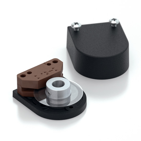
The E2 is a rotary encoder with a rugged glass-filled polymer enclosure, which utilizes either a 5-pin locking or standard connector. The internal components consist of a mylar disk mounted to a precision machined aluminum hub and an encoder module. The module contains a highly collimated solid-state light source and monolithic phased array sensor, which together provide a system extremely tolerant to mechanical misalignments.
The E2 is normally designed for applications of 10 feet or less. For applications requiring longer cable lengths, we recommend adding a PC4 / PC5 differential line driver or check out our E5 which has an optional differential output.
Attachment of the base to a surface may be accomplished by utilizing one of several machine screw bolt circle options. Positioning of the base to the centerline of a shaft is ensured by the use of our centering tool. The cover is securely attached to the base with two 4-40 pan head screws to provide a resilient package protecting the internal components.
Connection to the E2 product is made through either a 5-pin locking or standard connector. The mating connectors are available from US Digital with several cable options and lengths.
BROADCOM/AVAGO REPLACEMENTS:
US Digital's E2 encoder may be used as direct replacements for Avago HEDM-5500, HEDM-5600, HEDS-5500, HEDS-5600.
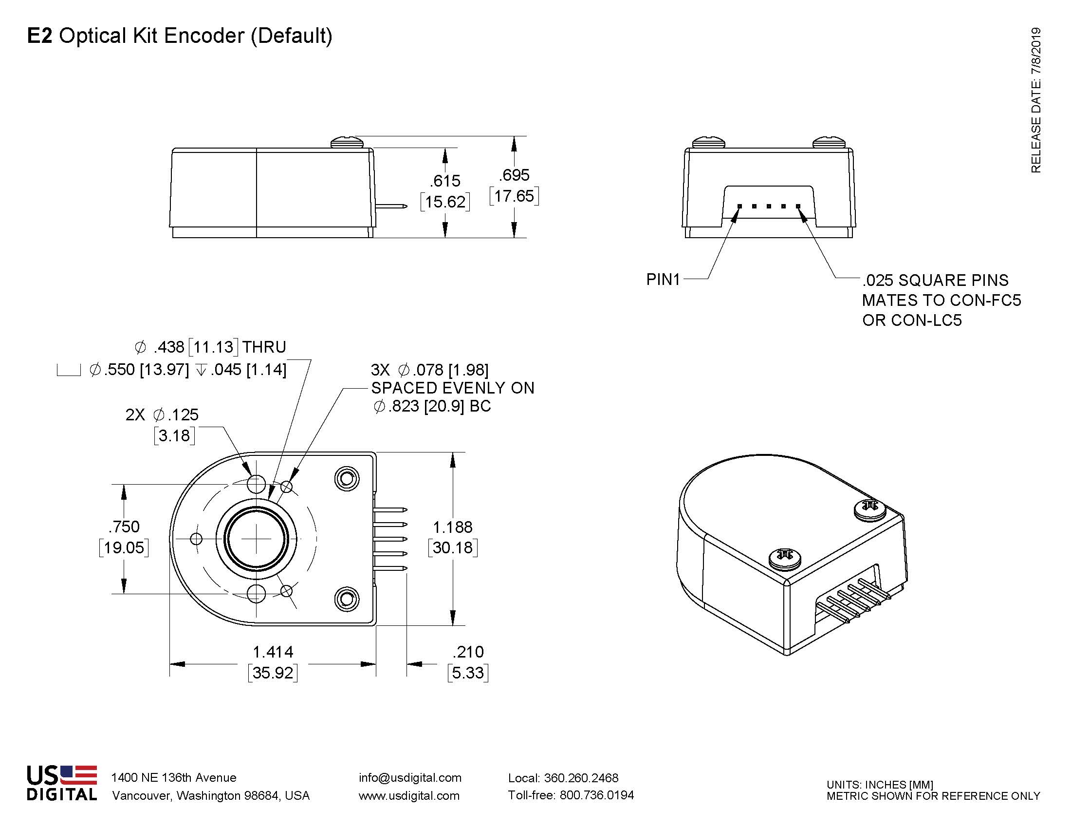
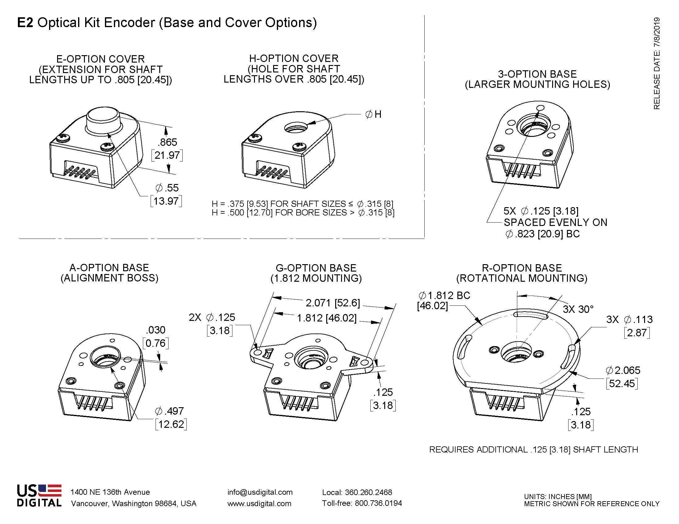
Mechanical Drawings
Specifications
ENVIRONMENTAL
| PARAMETER | VALUE | UNITS |
|---|---|---|
| Operating Temperature, CPR < 2000 | -40 to 100 | C |
| Operating Temperature, CPR ≥ 2000 | -25 to 100 | C |
| Electrostatic Discharge, IEC 61000-4-2 | ± 4 | kV |
| Vibration (10Hz to 2kHz, sinusoidal) | 20 | G |
| Shock (6 milliseconds, half-sine) | 75 | G |
MECHANICAL
| PARAMETER | VALUE | UNITS |
|---|---|---|
| Max. Shaft Axial Play | ±0.010 | in. |
| Max. Shaft Runout | 0.004 T.I.R. | in. |
| Max. Acceleration | 250000 | rad/sec² |
| For CPR ≤ 1250: Max. RPM (1) Max. A/B Frequency e.x. CPR=1250, Max. RPM=14400 e.x. CPR=100, Max. RPM=60000 |
minimum value of ((18 x 10^6) / CPR) and (60000) 300 |
RPM kHz |
| For CPR = 2000, 2048, 2500: Max. RPM (1) Max. A/B Frequency |
minimum value of ((21.6 x 10^6) / CPR) and (60000) 360 |
RPM kHz |
| For CPR = 4000, 4096, 5000: Max. RPM (1) Max. A/B Frequency |
minimum value of ((43.2 x 10^6) / CPR) and (60000) 720 |
RPM kHz |
| Typical Product Weight | 0.56 | oz. |
| Codewheel Moment of Inertia | 8.0 x 10^-6 | oz-in-s² |
| Hub Set Screw | #4-48 | |
| Hex Wrench Size | 0.050 | in. |
| Encoder Base plate Thickness | 0.135 | in. |
| 3 Mounting Screw Size | #0-80 | |
| 2 Mounting Screw Size | #2-56 or #4-40 | |
| 3 Screw Bolt Circle Diameter | 0.823 ± 0.005 | in. |
| 2 Screw Bolt Circle Diameter | 0.750 ± 0.005 | in. |
| Required Shaft Length (2)(3) With E-option (3) With H-option |
0.445 to 0.575 0.445 to 0.805 > 0.445 |
in. in. in. |
| Index Alignment to Hub Set Screw | 180 Typical | degrees |
| Technical Bulletin TB1001 - Shaft and Bore Tolerances | Download | |
(1) 60000 RPM is the maximum rpm due to mechanical considerations. The maximum rpm due to the module's maximum frequency response is dependent upon the module’s resolution (CPR).
(2) Add 0.125" to the required shaft length when using R-option.
(3) Including Axial play.
TORQUE SPECIFICATIONS
| PARAMETER | VALUE | TORQUE |
|---|---|---|
| Hub Set Screw | 2-3 | in-lbs |
| Cover Screw | 2-4 | in-lbs |
| Base Mounting Screw (#0-80) | 1-2 | in-lbs |
| Base Mounting Screw (#2-56) | 2-3 | in-lbs |
| Base Mounting Screw (#4-40) | 4-6 | in-lbs |
| Adapter Plate Mounting Surface (#2-56 screws) | 2-3 | in-lbs |
| Adapter Plate Mounting Surface (#4-40 screws) | 4-6 | in-lbs |
PHASE RELATIONSHIP
B leads A for clockwise shaft rotation, and A leads B for counterclockwise rotation viewed from the cover side of the encoder.
ELECTRICAL
- Specifications apply over the entire operating temperature range.
- Typical values are specified at Vcc = 5.0Vdc and 25°C.
- For complete details, see the EM1 or EM2 product pages.
| PARAMETER | MIN. | TYP. | MAX. | UNITS | CONDITIONS |
|---|---|---|---|---|---|
| Supply Voltage | 4.5 | 5.0 | 5.5 | V | |
| Supply Current | 27 | 33 | mA | CPR < 500, no load | |
| 54 | 62 | mA | CPR ≥ 500 and < 2000, no load | ||
| 72 | 85 | mA | CPR ≥ 2000, no load | ||
| Low-level Output | 0.5 | V | IOL = 8mA max., CPR < 2000 | ||
| 0.5 | V | IOL = 5mA max., CPR ≥ 2000 | |||
| 0.25 | V | no load, CPR ≥ 2000 | |||
| High-level Output | 2.0 | V | IOH = -8mA max. and CPR < 2000 | ||
| 2.0 | V | IOH = -5mA max. and CPR ≥ 2000 | |||
| 4.8 | V | no load and CPR < 2000 | |||
| 3.5 | V | no load and CPR ≥ 2000 | |||
| Output Current Per Channel | -8 | 8 | mA | CPR < 2000 | |
| -5 | 5 | mA | CPR ≥ 2000 | ||
| Output Rise Time | 110 | nS | CPR < 2000 | ||
| 50 | nS | CPR ≥ 2000, ± 5mA load | |||
| Output Fall Time | 100 | nS | CPR < 2000 | ||
| 50 | nS | CPR ≥ 2000, ± 5mA load |
ACCESSORIES
1. Centering Tool
Part #: CTOOL - (Shaft Diameter)
Description: This reusable tool provides a simple method for accurately centering the E2 base onto the shaft, promoting hub to base concentricity and thus accuracy.
It is recommended for the following situations:
- When using mounting screws smaller than #4-40.
- When the position of the mounting holes is in question.
- When using the 3-hole mounting pattern.
2. Hex Tool
Depending on the order packaging option, either a hex driver or hex wrench is included.
Part #: HEXD-050 (only included with -B or -1 packaging options)
Description: Hex driver, 0.050" flat-to-flat for #4-48 set screws.
3. Spacer Tool
A spacer tool is included for all packaging options.
Part #: SPACER-E2
4. Screws
Part #: SCREW-080-250-PH
Description: Pan Head, Philips #0-80 UNF x 1/4"
Use: Base Mounting
Quantity Required: 3
Screws are not included
Part #: SCREW-256-250-PH
Description: Pan Head, Philips #2-56 UNC x 1/4"
Use: Base Mounting
Quantity Required: 2
Screws are not included
Part #: SCREW-440-250-PH
Description: Pan Head, Philips #4-40 UNC x 1/4"
Use: Base Mounting
Quantity Required: 2
Screws are not included
Part #: SCREW-440-625-PH
Description: Pan Head, Phillips 4-40 UNC x 5/8"
Use: Cover Mounting
Quantity Required: 2
Screws are included
Part #: SCREW-448-063-SS
Description: Socket Head Set Screw, 4-48 UNC x 1/16"
Use: Hub/Disk Mounting for 5/16" - 10mm Bore
Quantity Required: 1
Screw is included
Part #: SCREW-448-125-SS
Description: Socket Head Set Screw, 4-48 UNC x 1/8"
Use: Hub/Disk Mounting for 2mm - 1/4" Bore
Quantity Required: 1
Screw is included
OUTPUT WAVEFORMS

Notes
- US Digital® warrants its products against defects in materials and workmanship for two years. See complete warranty for details.
- Cables and connectors are not included and must be ordered separately.
Configuration Options |
|||||||||||||||||||||||||||||||||||||||||||||||||||||||||||||||||
| E2 | - | CPR (Cycles Per Revolution) 32 50 96 100 120 192 200 250 256 360 400 500 512 540 720 800 900 1000 1024 1250 2000 2048 2500 4000 4096 5000 | - | Bore Size 079 (2.0mm) 118 (3.0mm) 125 (1/8") 156 (5/32") 157 (4.0mm) 188 (3/16") 197 (5.0mm) 236 (6.0mm) 250 (1/4") 276 (7.0mm) 313 (5/16") 315 (8.0mm) 375 (3/8") 394 (10.0mm) | - | Index IE (Index) NE (Non-Index) | - | Cover D (Default) E (Extended) H (Through-Hole) | - | Base D (Default) 3 (1/8" Mounting Holes) A (Aligning Shoulder) G (1.812" Diameter Bolt Circle) R (1.812" Diameter Bolt Circle, 3 Slot Rotational Mounting) | - | Packaging B (Encoders packaged in bulk. Every order includes one centering tool, hex tool and spacer tool. An additional set of tools is included for each 100 encoders ordered.) 1 (Encoders packaged individually. Every order includes one centering tool, hex tool and spacer tool. An additional set of tools is included for each 100 encoders ordered.) 3 (Encoders packaged individually. Every order includes one centering tool, hex tool and spacer tool per encoder.) | |||||||||||||||||||||||||||||||||||||||||||||||||||||
|
PLEASE NOTE: This chart is for informational use only. Certain product configuration combinations are not available. Visit the E2 product page for pricing and additional information. |
|||||||||||||||||||||||||||||||||||||||||||||||||||||||||||||||||