A2T Features
- 12-bit resolution field programmable from 2 to 4,096 codes per revolution (3,600 factory default)
- Full 360° range, 7 msec update time
- Low power drain of 18.5 mA max., and 2.5 mA in sleep mode
- Field programmable parameters such as setting zero position point (free demo software provided)
- EEPROM stores downloadable parameters
- 9,600 baud default data rate adjustable up to 115K baud
- 12-bit analog voltage output option (0 to +3.599 volts factory default setting. Field progammable up to 0 to +4.095 volts)
- Multi-turn mode (note: power must be maintained to prevent reset to zero)
- -25° to 70° C. operating temperature
- Simple, low cost
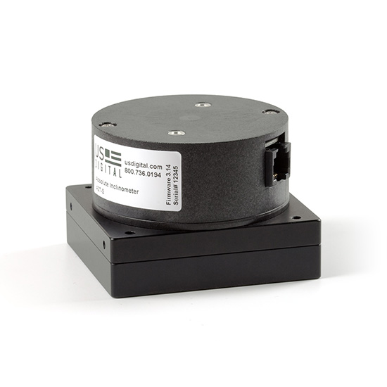
A2T Product Description
The A2T is a single axis, digital gravity angle sensor. The A2T serves as a full 360° range absolute tilt sensing programmable level with either digital or analog output. Internally, a rotary bar-coded disk is mounted to a weighted gravity-driven wheel. A micro-controller strobes an LED to transfer the bar code image onto an optical linear array which decodes the tilt angle. Magnetic damping provides a fast response and settling time. An internal EEPROM stores field programmable parameters such as resolution, zero position, direction swap, and mode.
The A2T communicates over an RS485 style serial bus utilizing US Digital's SEI (Serial Encoder Interface), which allows for simple, quick, and convenient networking of multiple SEI devices on a single network. PLCs, motion controllers, and computers can also reside on the SEI bus by using US Digital's SEI to USB interface device. For complete information about the SEI bus, please refer to the SEI Communications Protocol webpage. Cable CA-MD6A-SS-MD6 and the SEI-USB can be used to interface the A2T to a USB port.
The A2T is also available with an optional analog output. The analog output option provides a maximum voltage range of 0 to 4.095 volts with 12-bit resolution. The output voltage can be scaled by simple SEI commands to provide user-defined voltage ranges. From the factory, the analog output voltage is set to 0 to 3.599 VDC range. Please note that with the A2T analog output option, only one device may reside on an SEI bus.
Typical applications include heavy construction equipment, dredging machinery, mining equipment, solar tracking, and warehouse automation.
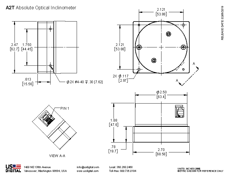
Mechanical Drawings
Specifications
ENVIRONMENTAL
| PARAMETER | VALUE | UNITS |
|---|---|---|
| Operating Temperature | -25 to 70 | C |
| Vibration (5Hz to 2kHz) | 20 | G |
| Electrostatic Discharge, IEC 61000-4-2 | ± 4 | kV |
MECHANICAL
| Parameter | Value |
|---|---|
| Settling Time | 0.6 to 1 sec. typ. |
| Pendulum Undamped Natural Frequency | 2 Hz typ. |
| Weight | 9.40oz. |
DAMPING

Damping affects settling time and overshoot. Standard damping will fit most applications. Double damping eliminates oscillation but settles to the final position more slowly. Some applications may require double damping to average out cyclic motion such as found in moving vehicles. Damping options can be specified when ordering.
ELECTRICAL
- Specifications apply over entire operating temperature range.
- Typical values are specified at Vcc = 12V and 25C.
| Parameter | Min. | Typ. | Max. | Units |
|---|---|---|---|---|
| Supply Voltage | 7.5 | 12 | 16 | V |
| Supply Current @ 12V supply Active Sleep |
14 2.5 |
18.5 |
mA |
|
| Analog Output Impedance | 51 | Ohms | ||
| Zero Scale Analog Voltage | 0 | 2 | 12 | mV |
| Full Scale Analog Voltage | 4.066 | 4.095 | 4.124 | V |
| Output Noise (Analog version) | 10 | mV rms | ||
| Differential Nonlinearity (Analog version) | -1.0 | 1.0 | LSB | |
| Integral Nonlinearity (Analog version) | -1.0 | 1.0 | LSB | |
| Absolute Accuracy (SEI interface version) | 0.18 | 0.25 | Degrees | |
| Angle tracking speed Single-turn mode Multi-turn mode |
3600 1800 |
RPM |
||
| Position Update Rate (1) | 7 | msec. |
(1) The internal microcontroller takes a snapshot of the disk every 7 msec. and stores the position in memory. It responds immediately to a "report position request" by sending the most recently computed position.
DEFAULT SETTINGS
| Parameter | Default value | Volatile? |
|---|---|---|
| SEI address | 0 | Non-volatile |
| Resolution | 3600 | Non-volatile |
| Origin offset | 0 | Non-volatile |
| Baud rate | 9600 | Volatile |
| Mode | 0 | (1) |
(1) Mode is always restored from non-volatile EEPROM on power-up; however, there are separate SEI commands for setting the RAM copy only, or both the RAM copy and the non-volatile EEPROM copy. For an explanation of the Mode bits, see SEI Absolute Encoder Communications Protocol.
ANALOG OUTPUT
The analog version of the A2T has a 12-bit DAC on the output which feeds to 2 lines that are otherwise used for the BUSY handshaking pair. This DAC has a full range of 0 to 4.095V which is 1 mV per count. The absolute position value the internal microcontroller sends to the DAC is the same as the digital value that it sends to the host over SEI. Since the resolution (which represents the number of CPR) is field programmable, the range of the DAC will also follow that setup. The default resolution is 3600 CPR, which yields 1 count per tenth of a degree. This makes the DAC output equal to 1 mV per tenth of a degree or 0 to 3.599V. If you want the DAC to have the full range to 4.095V, set the single turn resolution to 4096. This is easily done with the available software which runs on a PC.
Please Note: The BUSY handshaking lines are replaced by the analog output option. This means that only one device will be able to connect to the SEI bus when using the analog output option.
PIN-OUT
| PIN | DESCRIPTION |
|---|---|
| 1 | Ground |
| 2 | Busy+ Analog+ |
| 3 | Busy- Analog- |
| 4 | Power |
| 5 | Data L |
| 6 | Data H |
Notes
- Cables and connectors are not included and must be ordered separately.
- US Digital® warrants its products against defects in materials and workmanship for two years. See complete warranty for details.
Configuration Options |
|||||||||||
| A2T | - | Interface A (Analog) S (SEI) | - | Damping S (Standard) D (Double) | - | Housing D (Default) | |||||
|
PLEASE NOTE: This chart is for informational use only. Certain product configuration combinations are not available. Visit the A2T product page for pricing and additional information. |
|||||||||||