
How to pick the right encoder for your next project
You’re building a new machine, an electromechanical system, and you need to precisely control its motion. It’s critical that you get continuous positional feedback from the parts that move. You think you may need an encoder.
A quick search shows a huge range of encoder choices. How do you begin to narrow them down? How do you select the best type? Optical, magnetic, capacitive. Absolute, incremental. Once you’ve chosen a type, how do you choose from available options? Kit, shafted, hollow bore. Resolution, index, quadrature. Differential, single-ended. Analog, PWM, serial interface. Ball bearing, sleeve bushing. Plastic housing, metal housing. The list goes on.
Encoders are available in a range of technologies and with numerous options. Selecting the best encoder for a particular application requires making many choices.
You’ll see a lot of terms on data sheets; they can be illuminating—or cause further confusion. For a fighting chance to make the right choice, you need a roadmap. This white paper will give you the big picture; armed with that knowledge, you can make an informed encoder selection.
- We’ll begin with the world the encoder must fit into, and consider how that world’s conditions might affect your choices when you select an encoder.
- Next we’ll cover types of encoders and their options, and provide information for you to begin selecting an encoder.
- After you have an encoder picked out, we’ll do a double check and make sure it’s a good fit for the world you identified in the beginning.
But before we start down that road, let’s make sure the journey is necessary.
When Do You Need an Encoder?
Encoders close the feedback loop, and tell you exactly what a moving part in your system is doing. But that’s not always necessary; many systems operate “open loop”. Since encoders come at a cost in time, money and complexity, they may not be the best fit for all situations, particularly where encoder signals are not really necessary.
Stepper Motors – In many stepper motor applications, for example, it’s enough to command the motor to go a certain number of steps, and assume it gets to its destination. The two main concerns with stepper motors are resonance and missing steps; either can cause a stepper motor to lose position. In many applications, however, proper motor sizing can overcome those two concerns. If your system can run open loop, this may be all you need.
Commutation – If you think you need position information from an encoder to commutate your motor, there may be cheaper alternatives. Some motors are available with built-in Hall sensors, specifically designed to tell a motor driver which coils should be energized at any particular moment.
The EC35 Optical Commutation Kit Encoder provides A/B/Z incremental outputs and U/V/W outputs for brushless motor commutation.
Switches – simpler mechanisms like limit switches or proximity switches are sometimes all that are necessary for motion control signals.
If you consider the options above, please note that they are very limited in what they are able to do. So if you need accurate position information, or want to know how fast or in what direction something is moving, or the distance it has traveled—then you need an encoder.
If you need an encoder, next step is to consider what kind of application it will be used in.
The World and Your Encoder
Before zeroing in on specific encoder choices, it’s critical that we first look at the world your encoder must fit into. No encoder is a stand-alone device. You need to think about the conditions surrounding your encoder; this will prepare you for choices later in this white paper.
What does your encoder’s future world look like?
Type of Motion – an encoder senses motion in an electromechanical system. Your encoder will be in contact with a part of the system that moves. Is that motion linear or rotary?
Speed – how fast is the motion? High speeds can cause difficulties, while extremely slow speeds come with their own set of problems.
Data Acquisition System (DAS or DAQ) – your encoder will send signals to a DAQ system of some kind (PLC, motion controller, computer). What type of input signals does your DAQ system expect from the encoder?
Power Supply – the encoder needs power to operate. How will you provide that power?
Cable Lengths – some encoders are optimized for sending signals over short cable runs. Others are able to send signals for thousands of feet or meters. Which situation matches your application?
Encoder Mounting Location – will the encoder be on the motor, on the load, or somewhere in between? A different type of encoder could be used in each of those situations.
Mechanical System – is it direct drive, or are gears, leadscrews or actuators involved? System accuracy, among other things, depends on the answer.
Design Flexibility – you’ll have a broader range of encoder choices if the system is still being designed. If your design is already set, your available encoder choices will be limited.
Powering Up – do you need to know the absolute location of the shaft/disk at the moment your system turns on? If you can permit your system to perform a homing move, you’ll have more encoder choices.
Environment – is your application in a harsh industrial setting, or a comfortable office environment? Encoders built to handle dirt, dust or high humidity may look very different from an encoder built to work in a laser printer in an office, for example.
How Many – are you building a single system for use in your own factory? Or are you building thousands of systems for shipment around the world? The time it takes to assemble and install various encoders might be critical if you’re building thousands of systems.
Cost – it may not be part of your encoder’s world, but cost is definitely part of your world. Encoders range in price from less than a dollar to thousands of dollars. How much can you spend?
With a firm understanding about all of the above, let’s see what type of encoder might fit into your application’s world.
Encoders and Their Options
Every point presented above puts a different demand on an encoder. To satisfy the range of requirements, most manufacturers produce a variety of encoders. We’ll look at available choices and options to customize an encoder for your application.
As you go through the following sections, use the information to begin selecting an encoder for your system. We provide check boxes at the end of each section to help you keep track of your decisions.
Is the Motion in Your System Rotary or Linear?
The first broad divide in your choices comes right at the start, and it’s based on the type of motion in your application. Linear motion occurs in a straight line—back and forth. Linear encoders are made to be used in applications like reporting the position of a forcer in a linear motor, or distance in digital calipers.
Rotary encoders are often attached to a motor, and can report motor shaft position. They can also be used with anything that rotates; for example, they can report the angle of flaps on an airplane, or the angle of a robot’s arm.
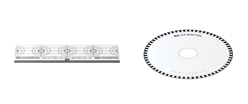
A linear encoder strip (left) is used with linear encoders. An encoder disk (right) is used with rotary encoders.
The information from either type of encoder—linear or rotary—can be used by a motion controller to calculate position, speed, distance and direction.
Choose a type of encoder motion:
▢ Rotary encoder
▢ Linear encoder
Which is best for your application? An Optical, Magnetic or Capacitive Encoder?
Three main technologies are used in encoders.
Optical Encoders – are the most commonly used type of encoder. Inside the encoder is a disk with opaque and transparent areas, usually in a pattern of lines and windows. (Linear encoders use a strip instead of a disk.)
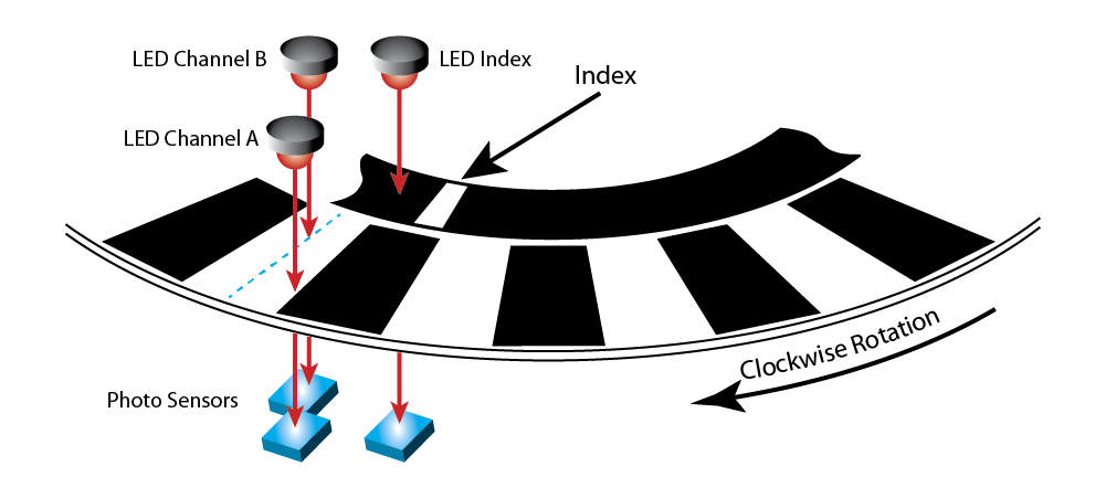
In optical encoders, lines block the light; windows let the light pass through to a sensor. The output goes high when the sensor receives light, and it goes low when the light is blocked.
An LED array shines light at the disk: lines block the light, and windows let light pass through to a photo sensor on the other side. In most encoders, signals from the sensor are processed with onboard signal conditioning circuitry, and transmitted to the motion controller.
Optical encoders can be manufactured with very high resolution and accuracy. They function best when nothing gets in the way of the light path. Environments with high humidity, moisture or excessive dust can cause problems for optical encoders, unless addressed by specialty packaging. In addition to a choice of standard resolution options, some vendors will also make custom resolutions and custom packaging available.
Magnetic Encoders – typically have a magnet attached to a rotating shaft.
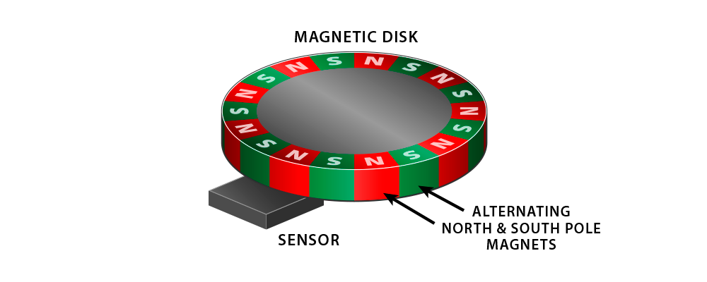
Magnetic encoders have a rotating magnet inside, and a sensor that detects the positions of the magnetic field.
A stationary sensor detects the north-south field lines from the magnet, and reports the angle of the magnetic field as the shaft rotates.
Since they don’t depend on light like optical encoders, magnetic encoders function well in the humid, moist or dusty settings that cause problems for optical encoders. They often use less power. However, magnetic encoders can be sensitive to stray magnetic fields which might be coming from the motor, or even other encoders nearby. In some cases you might need to install magnetic shielding to block stray fields to isolate the encoder.
Capacitive Encoders – this is a newer technology. It detects change in capacitance, and relates that change to position. Inside the encoder, a transmitter sends a high frequency signal past a rotor, to a receiver. The rotor modulates the signal, and the receiver translates the modulated signal which is then sent to the motion controller.
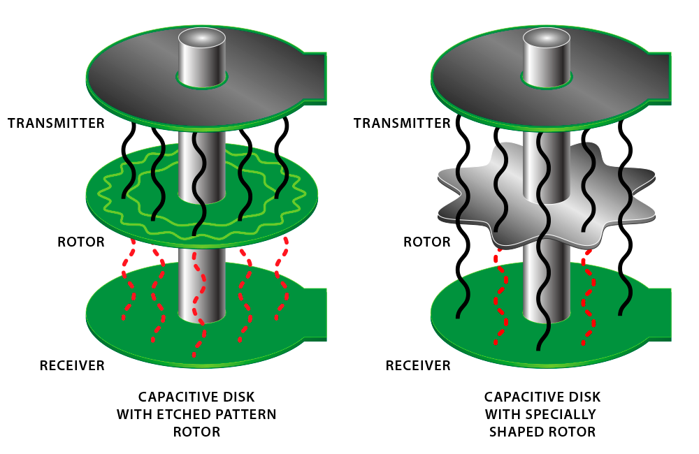
A capacitive encoder contains a transmitter that emits a high frequency signal, a rotor that modulates the signal, and a receiver that translates the signal and sends it to a motion controller.
Capacitive encoders draw less current than optical and magnetic encoders, and do well in environments with dust, moisture or condensation. Maximum speeds of capacitive encoders are often less than optical encoders, and may affect size limitations, but depending on your application that might not be a factor.
NOTE: Some vendors make claims as to their technology being the best in many or all applications. As this is an educational document, our recommendation is to check the data sheets to compare the encoder specifications most important in your application.
Choose a type of encoder for your system:
▢ Optical encoder
▢ Magnetic encoder
▢ Capacitive encoder
What’s the Difference Between Shafted, Kit or Hollow Bore Encoders?
You can choose from three main shaft options for rotary encoders.
Shafted Encoders – sometimes known as ‘bearing encoders.’ Internally, the encoder disk is mounted to a shaft which protrudes from the encoder housing. Shafted encoders can be used in three different ways:
- You connect the encoder shaft to your system, directly to a motor shaft. To accommodate axial or radial runout, or misalignment between two shafts, you might need to use a flexible coupling or mount.
- You connect the encoder via gears or sprockets added to both shafts.
- The encoder is used as a knob on a front panel Human Machine Interface (HMI).
Shafted encoders can mount directly to a motor shaft, connect via gears or sprockets to another shaft, or be used on a front panel Human Machine Interface (HMI).
The shaft can be round, or have a flat on one side, which is helpful when connecting the encoder shaft to a coupler.
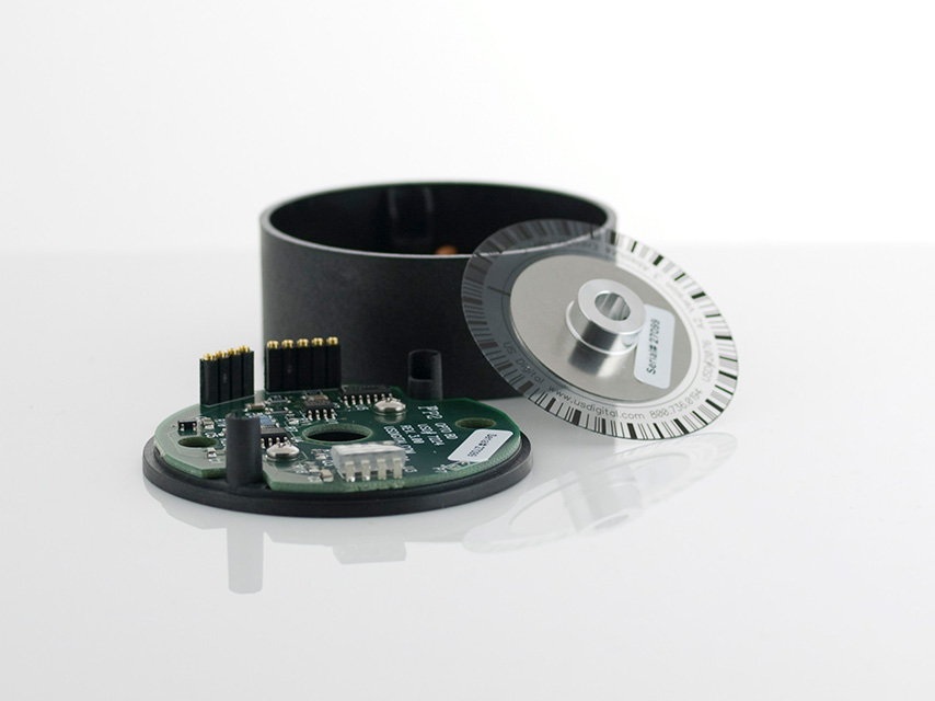
Encoder Kits – also known as modular encoders. The encoder has no shaft; instead, it has several components, intended to be attached to a shaft such as the rear shaft of a motor.
- The base mounts to a motor housing or stationary plate
- The encoder disk attaches to the motor’s shaft
- The encoder sensor module attaches to the base
- The cover is installed over the whole assembly.
NOTE: the description above is for an optical encoder. You may find that magnetic encoders have fewer components and capacitive encoders have more components.
Encoder kits are assembled from components. They have no internal bearings; instead, they depend on the motor shaft’s bearings.
Encoder kits have no bearings—they depend on those of the motor shaft—which often makes them more cost effective. They can potentially be used at a higher RPM, since they aren’t speed-limited by their own internal bearings (as shafted encoders are).
Hollow Bore Encoders – also known as hollow shaft or thru-bore encoders. These encoders have their own internal bearings, which encircle a shaft with a hollow bore. The encoder’s hollow shaft mounts over the motor’s shaft (or another shaft in the system).
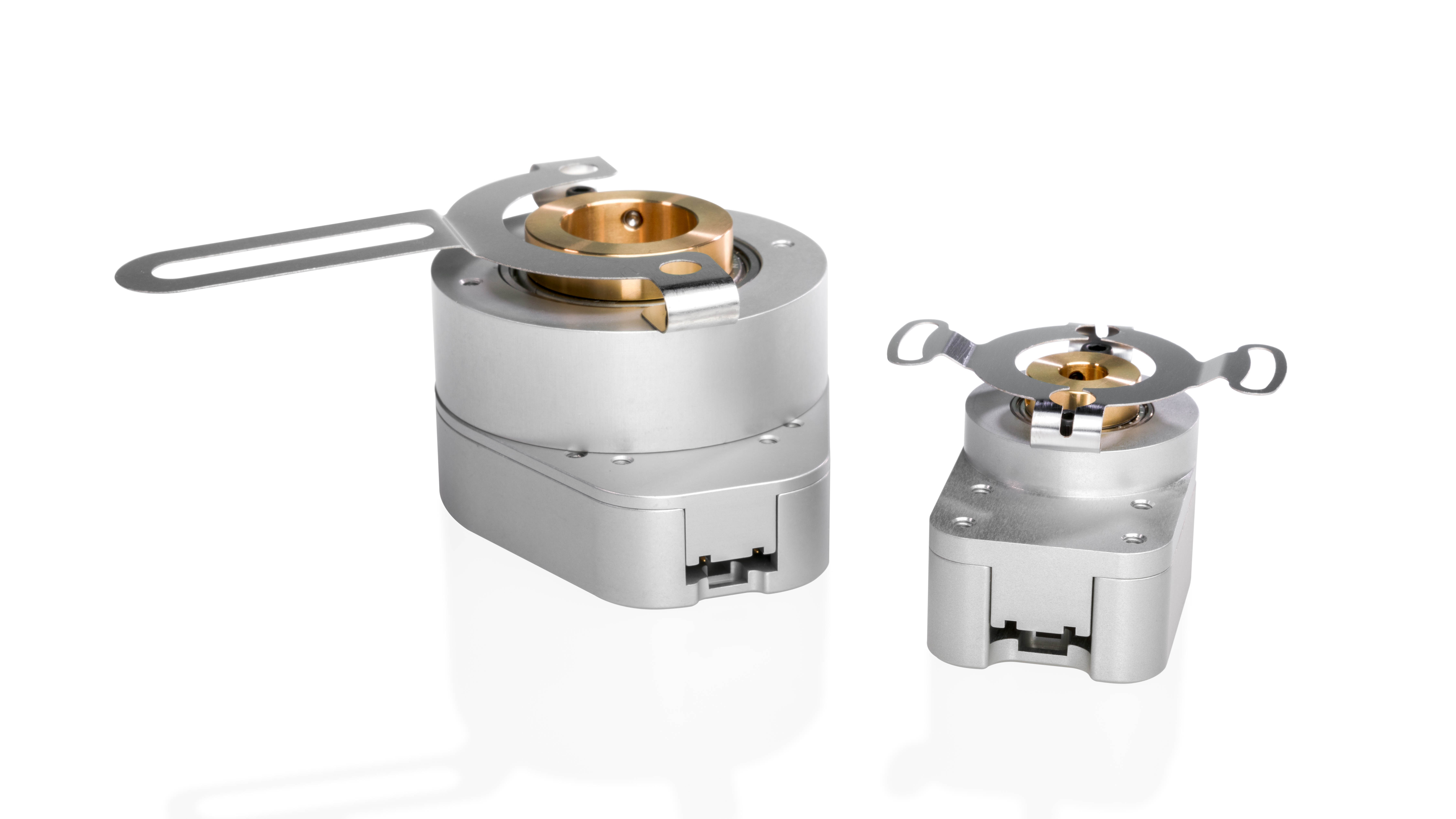
Hollow Bore Encoders have internal bearings and a shaft with a hollow bore. The hollow shaft mounts over the motor’s shaft or another shaft in the system. A flexible tether is used for mounting.
The encoder can be equipped with a flexible tether which makes the encoder more tolerant of shaft runout than a standard encoder kit.
Choose a shaft style for your system:
▢ Shafted encoder
▢ Encoder kit
▢ Hollow bore encoder
Do You Need an Incremental, Absolute or Pseudo-Absolute Encoder?
Encoders can report position information in two very different ways, with a third choice that’s a hybrid between the other two.
Incremental Encoders – report relative position. As the internal disk rotates or a linear strip moves, the encoder will transmit a high or low pulse for each “increment” of motion. (For optical encoders, the size of that increment is related to the pattern of lines on the disk.) Two output channels, often called Channel A and Channel B, are typically used to send signals to a motion controller. The channels are offset from each other by 90 electrical degrees; this phase difference, known as quadrature, allows the motion controller to determine direction of motion.
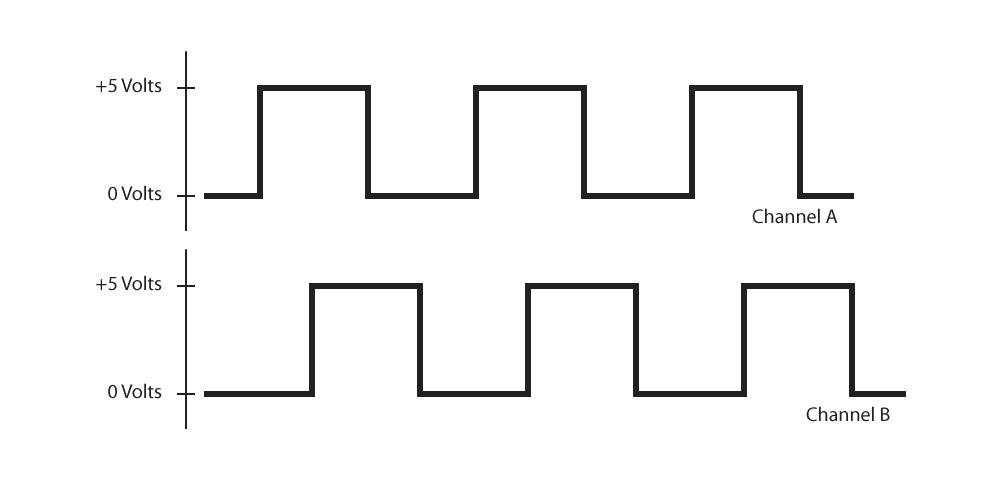
Incremental encoders transmit a high or low pulse for each increment of motion. To determine direction of motion, a second output (Channel B) is added, offset from Channel A by 90 electrical degrees.
The pulses are simple to process, which makes incremental encoders good for position and speed control. The encoders are good at high speeds, because they can continuously stream output pulses. They are simpler than absolute encoders, and therefore lower cost. However, unlike absolute encoders, incremental encoders will lose position information if power is lost or cycled.
Absolute Encoders – report absolute position. This is true even if power is cycled. Every sector of the internal disk has a unique pattern; outputs from the encoder transmit information which the controller can use to determine the exact position of the mechanical system. Many output types are available, including analog voltage variation, Pulse Width Modulation (PWM), and serial communication interfaces.
The kit version of the A2K Absolute Optical Encoder can be assembled onto existing shaft and bearing assemblies. The encoder reports the shaft angle within a single 360° rotation of a shaft.
Single-turn absolute encoders report position within one revolution of the encoder disk. Multi-turn absolute encoders can also keep track of the total number of turns. Multi-turn models need a battery backup, gears or other method to preserve position information if power is cycled.
Absolute encoders require internal circuitry that is more complex than incremental encoders, which makes them more expensive. Also, because absolute encoders don’t continuously stream their data like incremental encoders do, they are sometimes not as well suited for high-speed applications.
Pseudo-Absolute Encoders – are incremental encoders with a third channel added, which is called an Index; this gives them the ability to act like absolute encoders.
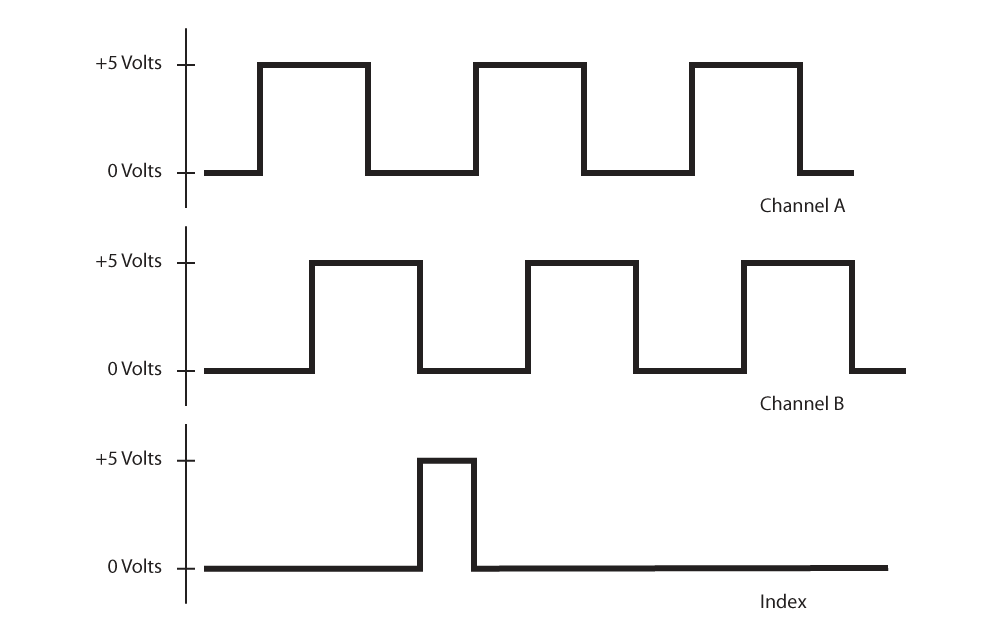
A third output, called Index, occupies its own band on the encoder disk and provides absolute position information at a single location.
Index is a mark, located on its own band on the encoder disk or linear strip. The encoder is able to keep track of its location by how far it is from the index—but only until the power goes off. If power fails or cycles, you will lose all position information. Your system will need to perform a homing move to find the index position, and start counting from that point.
If in your application you need to know where the disk is in its rotation, but can allow a homing cycle as needed, a pseudo-absolute encoder might be a good choice for you.
Choose a type of position reporting for your encoder:
▢ Incremental encoder
▢ Absolute encoder
▢ Pseudo-Absolute encoder
What’s the Best Resolution for Your Application?
Incremental encoder output is most commonly a square wave—a series of high and low pulses. The term resolution specifies the number of times the output signal goes high per revolution. It’s measured in units of Cycles per Revolution (CPR), and can range from low numbers like 32 to much higher resolutions like 10,000 and even some extremely high resolutions like 100,000 and more. NOTE: Linear encoders are measured in units of Cycles per Inch (CPI) or Lines per Inch (LPI).
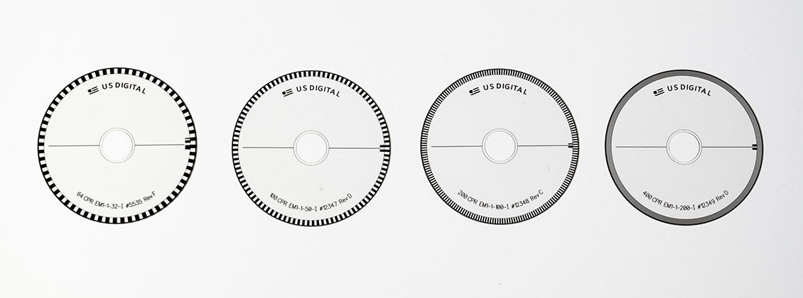
With some optical encoders you can literally see the resolution right on the encoder disk. Lines on the disks above result in resolutions of 64, 100, 200 and 400 CPR (left to right).
Absolute encoder resolution refers to the number of positions per revolution that can be reported, often specified in bits. For example, a 10-bit absolute encoder can report 1,024 positions; a 12-bit encoder can report 4,096 positions.
In either case, resolution tells you the smallest distance that can be measured: divide the total distance of 360° mechanical degrees by the number of cycles per revolution, and the answer will be mechanical degrees per cycle or position.
Lower resolution encoders can be used in applications where approximate positioning is acceptable, or in high-speed applications where bandwidth limits take effect. High resolution encoders are useful in applications where exact positioning is critical, when motion occurs at extremely slow speeds, or when very small distances are measured. What is the smallest measurement you need to make in your application?
Manufacturers have a limited number of stock resolutions for any particular model of encoder. If you need a specific resolution but don’t see it listed, ask the manufacturer if they can make a custom resolution for you. Some vendors do custom resolutions as a matter of course.
Should you always select the highest resolution available? Not necessarily; here are some reasons higher resolution may not be the best choice.
- Cost: higher resolution may be more expensive
- Time: it takes time to read each cycle. Higher CPR = more time
- Jitter: sensitive systems may over-respond to high CPR information
- High Velocity Applications: less time to read each cycle
- Size: higher resolution encoders may be larger
The term resolution does not mean the same thing as accuracy. In error, many people use the two terms interchangeably, but they refer to different things. We’ll explain more in the next section. (Check out our white paper on encoder resolution, accuracy and precision for a more in-depth explanation.)
Choose your preferred resolution:
▢ ___________ CPR (rotary encoder)
▢ ___________ CPI or LPI (linear encoder)
▢ ___________ Bits or Positions per revolution (absolute encoder)
How Much Accuracy Do You Need?
When you command your system to move to a particular position and then stop, the encoder reports the final position. The term accuracy describes the difference between target position and actual position. They are often not the same; actual position may be off from target position by some amount, as shown in the encoder’s accuracy specification.
Now we can clear up the confusion between resolution and accuracy
- Resolution is the smallest distance that can be measured
- Accuracy is how close you are to a target position The terms measure different parameters.
Accuracy for rotary encoders is measured in degrees, arcminutes or arcseconds.
- Less accurate encoders are measured in degrees
- Medium accuracy encoders are measured in arcminutes
- High accuracy encoders are measured in arcseconds
There is a cost associated with accuracy.
- Less accurate encoders can be purchased for a few dollars each
- Medium accuracy encoders cost more, in the range of tens or hundreds of dollars
- High accuracy costs the most, and can be in the range of thousands of dollars
IMPORTANT - When considering accuracy it is essential to note that in most systems, other variables such as gear backlash or ball screws will play a much bigger role in total system accuracy than the encoder. For most applications medium accuracy encoders are adequate.
Choose an accuracy range:
▢ Low accuracy
▢ Medium accuracy
▢ High accuracy
Which Encoder Output Type Does Your System Need?
Encoders report position information by transmitting output signals to a data acquisition system such as a motion controller. For each type of encoder, several kinds of outputs are available. In most cases, you will choose an output type based on your system’s needs.
Incremental Encoders – outputs can be single-ended or differential.
- Single-ended outputs are typically 0 – 5VDC, referenced to ground; they’re okay for short cable runs
- Differential outputs consist of two outputs per channel, mirror images of each other. For example, see Channel A+ and Channel A- in the drawing below. Differential outputs provide better electrical noise immunity than single-ended outputs, and are better for long cable runs.
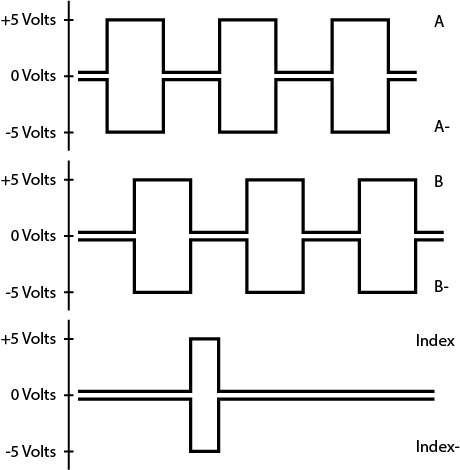
Differential outputs provide two outputs per channel, mirror images of each other, which provide better immunity to electrical noise over long cable lengths.
Absolute Encoders – many choices are available for outputs.
- Serial communication interface, e.g. SEI, SSI, Profibus, EtherCAT, Profinet etc.
- Analog voltage output, e.g. 0 – 5VDC; the voltage is scaled to represent absolute position.
- Pulse Width Modulation (PWM) output; the width of the pulse represents absolute position.
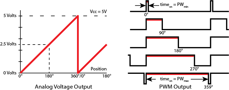
With an Analog Voltage Output (left), voltage represents absolute position. With a PWM Output (right), the pulse width represents absolute position.
The main selection question for choosing encoder outputs is: what does your data acquisition system require? If you’re considering an encoder that’s available with either PWM or analog voltage outputs, but your motion controller requires analog voltage inputs, then the choice is obvious—order the encoder with analog voltage outputs.
Choose encoder outputs, based on your data acquisition system’s needs:
Incremental Encoder Options
▢ Single-ended
▢ Differential
▢ ___________ Other
Absolute Encoder Options
▢ Analog voltage
▢ PWM output
▢ Serial communication
▢ ___________ Other
What is Your System’s Available Power Range?
Encoders need power to operate. For example, some models accept 5VDC or lower; others require input power in the range of 9.5 – 30VDC.
What power can your system provide? The answer may determine which encoder you choose but it may also indicate that another power supply is required. Please note that some vendors have cable adapters available which allow you to use a 5VDC encoder in a 24VDC system. Check with your supplier for similar options.
Choose power available from your system:
▢ 5VDC or lower
▢ 9.5 – 30 VDC
▢ ___________ Other
▢ Will need adapter (e.g. convert 24VDC from system to 5VDC for encoder)
At What Speed Will Your Encoder Operate?
How fast will the encoder disk move in your system? Speed has many implications, and it can affect encoder performance in several ways.
Mechanically, the encoder will have a maximum RPM at which it can operate. This might influence you when choosing between an encoder with bearings or one with a sleeve bushing. Or, you might choose an encoder kit instead of a shafted model, since the kit has no bearings of its own; it takes advantage of the bearings on the shaft of the motor or other device on which it is mounted.
Electrically, speed can affect the bandwidth of the system. Signals from the encoder to the motion controller may degrade at high speeds, since there is less time to report each position. Check the data sheet to see if your application’s required RPM will be an issue.
Choose a speed range: Write RPM or in/sec in blank space next to selected speed
▢ Extremely slow ___________
▢ Slow ___________
▢ Medium ___________
▢ Fast ___________
▢ Extremely fast ___________
Which Encoder Housing Style Meets Your Needs?
Options abound for encoder housings.
Material – encoder housings can be machined from metal or injection molded from plastic. Metal and some rugged plastic versions are more suitable for environments where the encoder is subject to abuse.
Seal – the housing can be non-sealed, or sealed with an O-ring to help keep contaminants from inside the encoder. Be aware that a sealed housing will have more shaft torque (drag), which may reduce the maximum RPM for the encoder.
Opening in Cover – the cover on an encoder kit is usually solid, but may be available with a hole as an option.
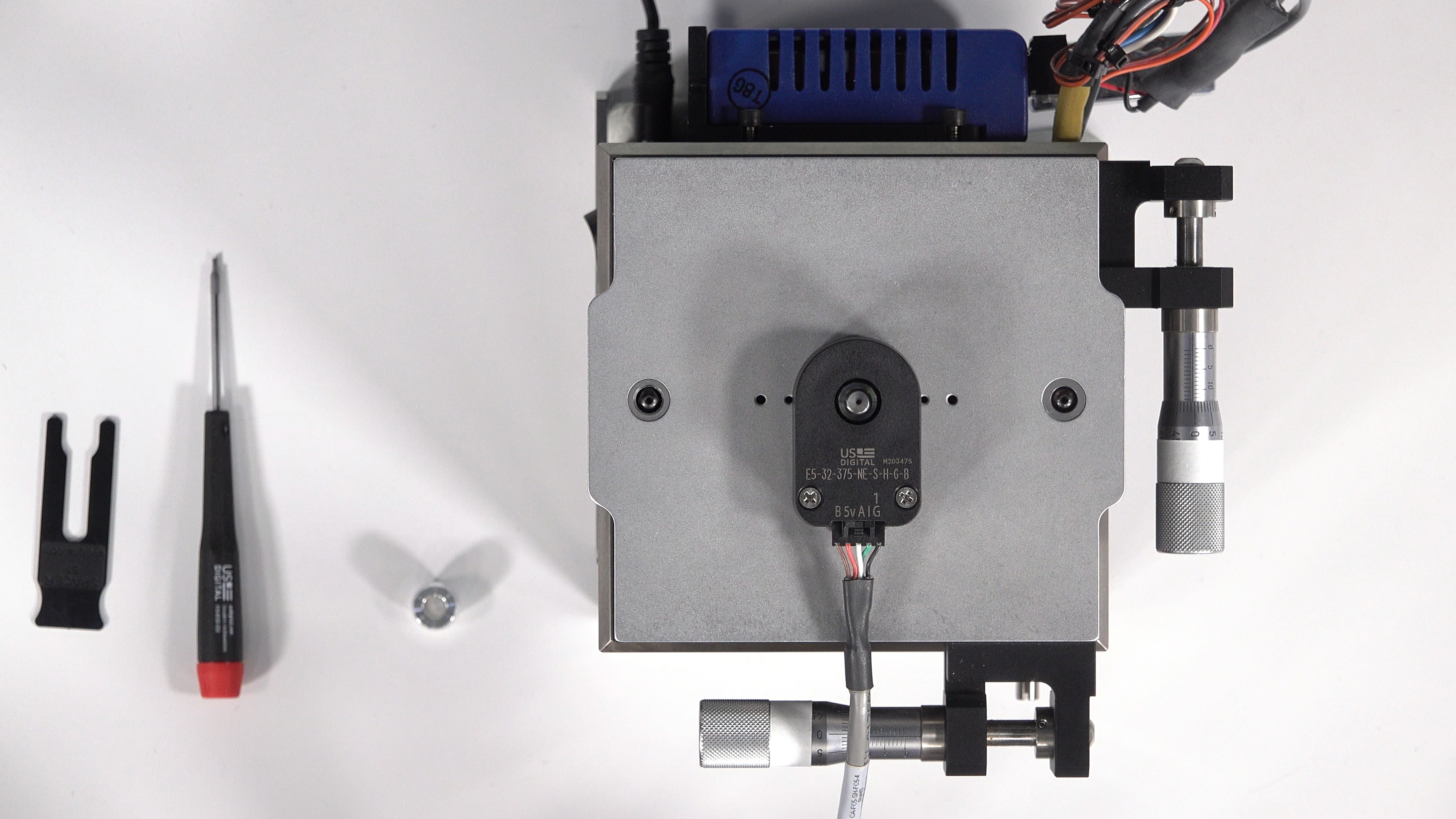
The cover of an E5 Optical Kit Encoder is usually solid. The cover on the E5 encoder in this photo has an optional hole, which allows the shaft of the device below to extend through the encoder’s cover.
The hole allows the motor shaft to protrude through the cover, if required.
Without Housing – you can order encoder kits without housings from some manufacturers, who allow you to buy only the components you need, such as a hubdisk assembly and encoder module. If your application is suitable, eliminating the housing might save space in tight locations or reduce cost.
Mounting Options – the housing may be designed to align with a standard bolt circle on a motor, which makes mounting the encoder easier. Some encoders have a choice of options with and without ears to match common hole patterns. It may be necessary to add holes to the motor or bracket for mounting of the encoder. Certain hollow bore encoders have a flexible tether used for attaching the encoder to the motor (tethers are visible in the earlier photo of hollow bore encoders, above). Some manufacturers also offer customized mounting options upon request.
Choose encoder housing options: (select all that apply)
▢ Plastic
▢ Metal
▢ Non-sealed
▢ Sealed
▢ Closed cover
▢ Opening in cover
▢ Without housing – order components only
▢ Mounting – standard bolt circle
▢ Mounting – ears to match hole pattern
▢ Mounting – must add holes to motor or bracket
▢ Mounting – fits over motor shaft (hollow bore encoder)
▢ Flexible tether
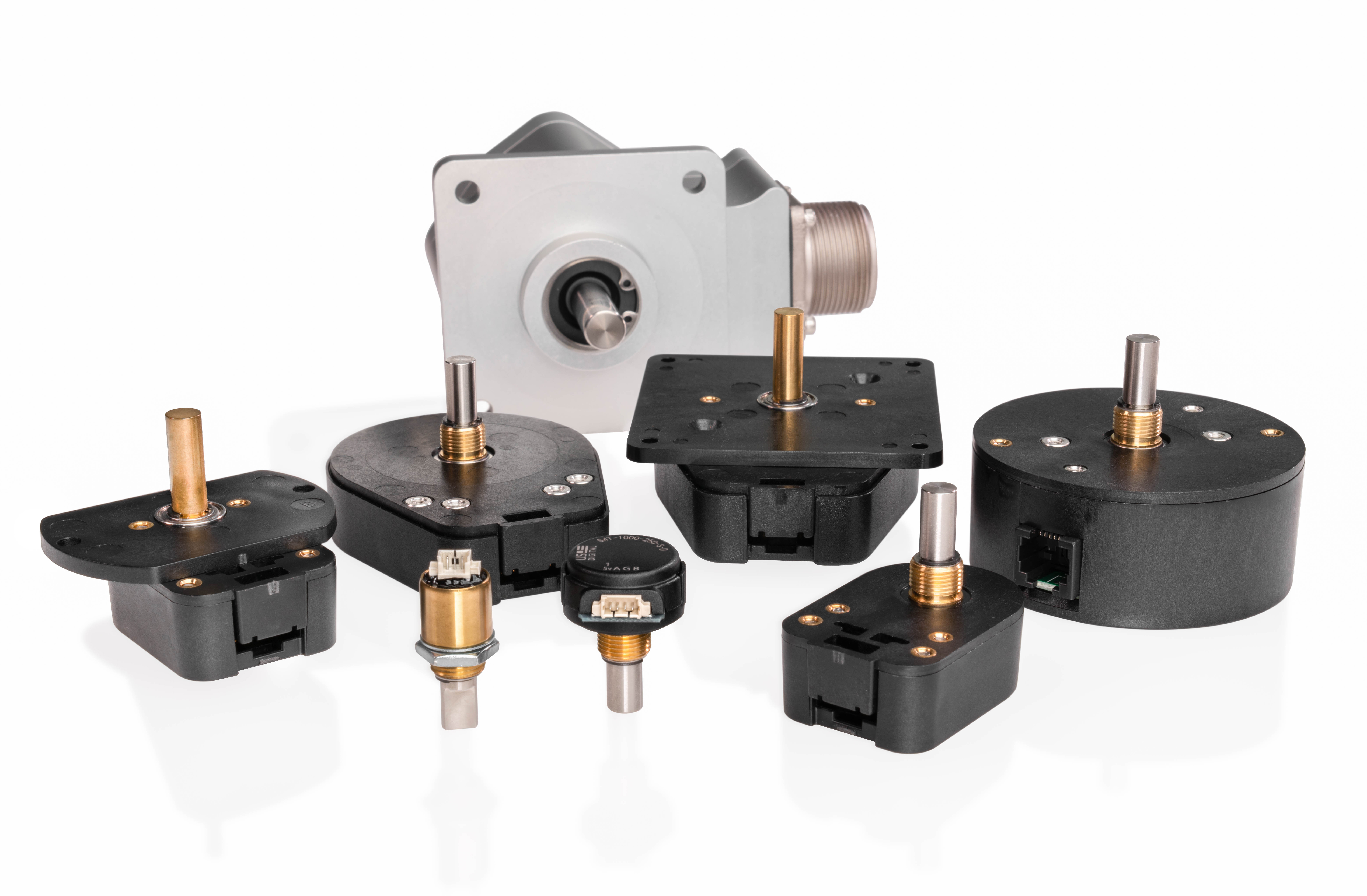
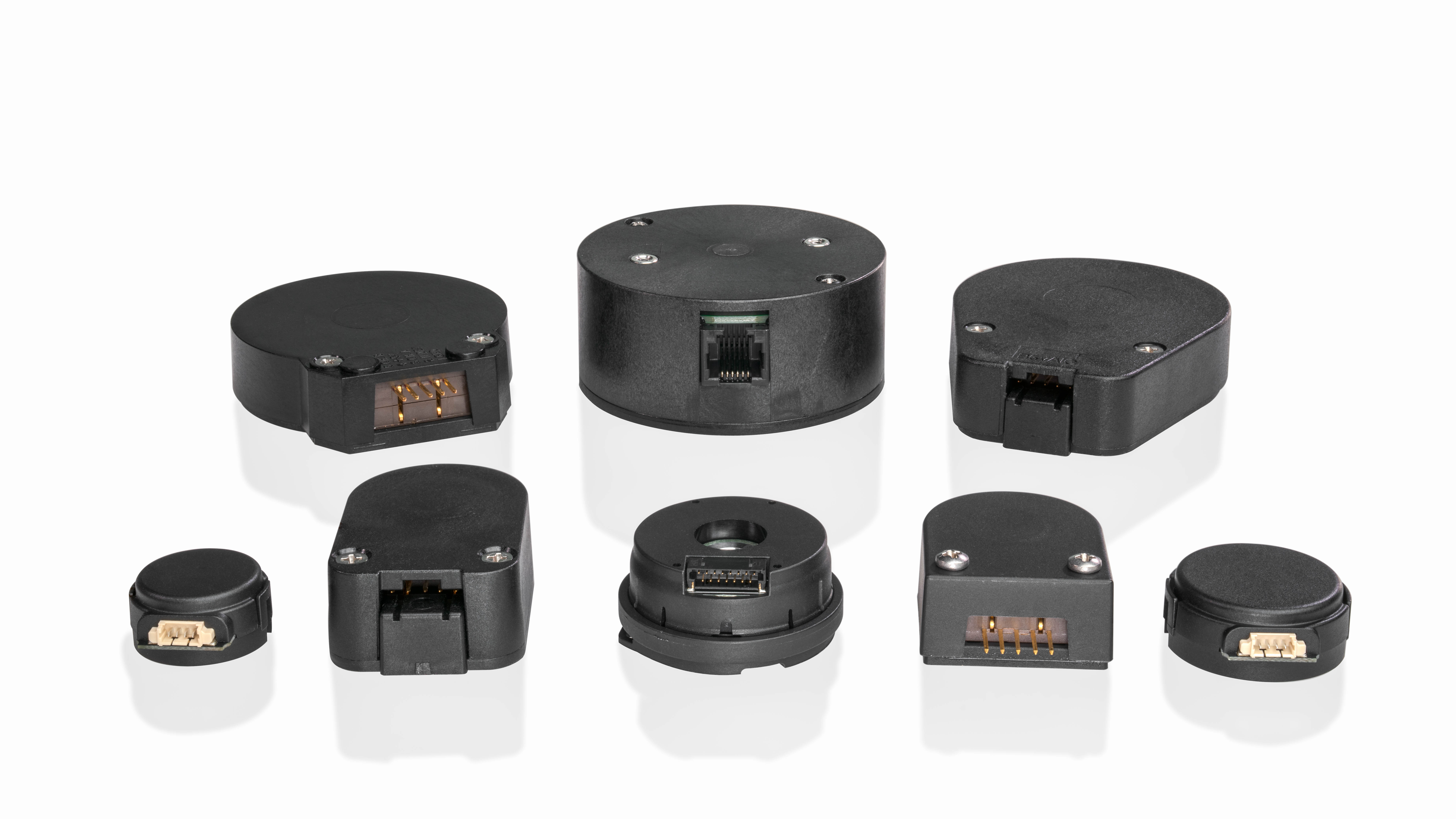
Which Encoder Size Do You Need?
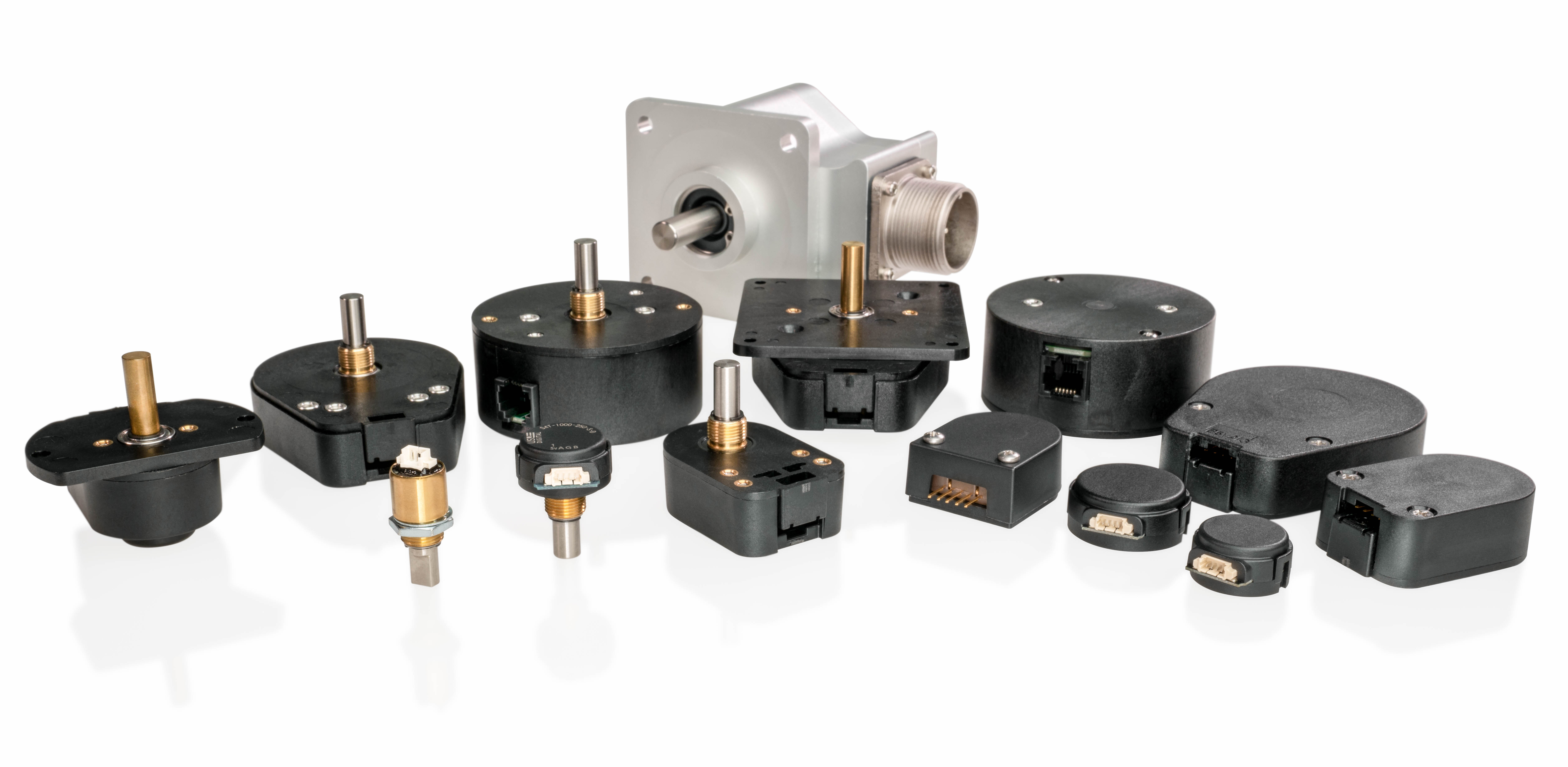
Encoders come in a range of sizes. The diameter of the internal encoder disk, the type of housing, the connector style and other factors affect the size of the encoder.
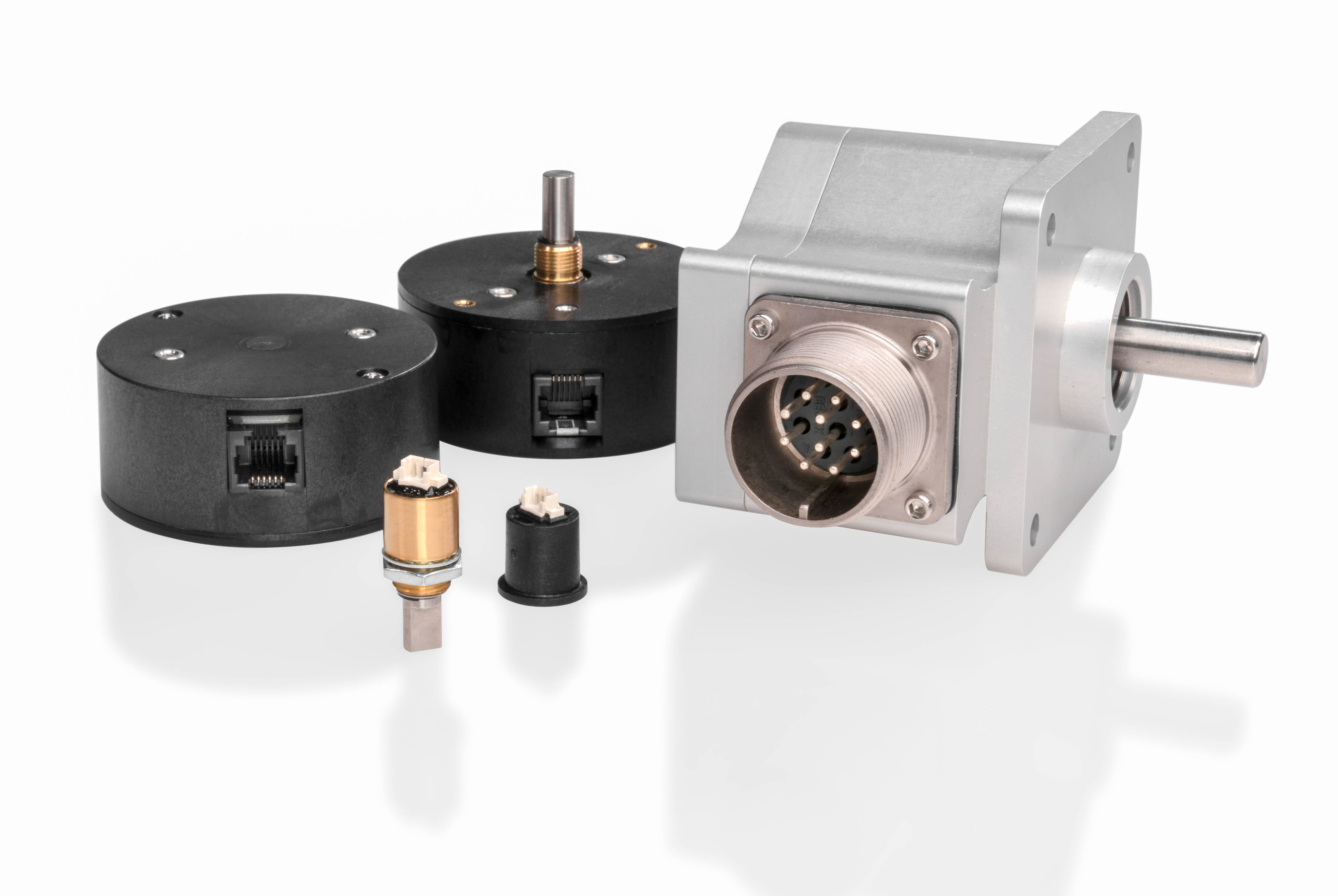
Large, medium and miniature size encoders are seen here.
Large – encoders built for rugged conditions often require sturdy housings, which add to encoder size. In some technologies higher resolution encoders require larger encoder disks, which can result in larger encoders. Dimensions of large encoders can be 4 inches and even much greater.
Medium – many encoders use internal disks that are one or two inches in diameter, resulting in typical maximum encoder dimensions ranging from 1 – 3 inches
Miniature – manufacturers have responded to the growing trend of miniaturization in electronics by producing encoders much smaller than one inch in size. It used to be true that a smaller encoder would have very limited resolution, but with technological advancements the resolution of smaller encoders can be remarkable. Fortunately, we see smaller encoders available now that weren’t available just a few years ago.
How much space is available for the encoder in your application? Your answer could definitely help guide the decision as to which encoder to use.
Choose an encoder size:
▢ Large (ample space is available for the encoder)
▢ Medium (moderate space is available for the encoder)
▢ Miniature (very little space is available for the encoder)
Use Your Choices and Select an Encoder
If you’ve filled out the check boxes above, then you have a good idea of what type of encoder you need, and which options are best for your application. Use that information now: examine manufacturers’ encoder literature and data sheets, and try selecting an encoder.
If you need more detailed information or have further questions, don’t hesitate to contact a manufacturer’s customer support staff. Most reputable manufacturers will be happy to answer questions and help guide you through the selection process.
Encoder Meets World
After we considered your encoder’s world in the beginning of this white paper, we looked at specific encoder types and options in the next part. This gave you enough information to try selecting an encoder. With your trial selection in mind, let’s revisit your encoder’s future world, and see how well your selection stacks up against conditions it might find there.
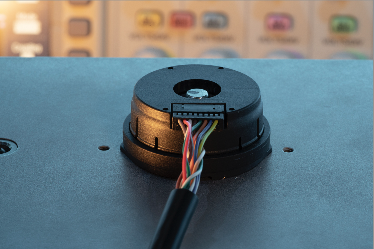
Connectivity – Cabling
Cabled vs. Pins/Connector – is a cable already connected to your encoder? If not, your encoder probably has pins to which you must make connections. You’ll need a cable, a connector for the encoder end, and perhaps a connector for the controller end. Would your application benefit by using a latching connector? Will you assemble these components yourself? Perhaps you can order everything, the entire cable assembly, from your encoder manufacturer; many provide that service.
Data Acquisition System Cables – what are your motion controller’s cabling requirements? Make sure your encoder outputs match the inputs at the controller (single-ended, differential; analog 0 – 5VDC, PWM etc.) and that you have the connectors needed, or know where to get them.
Cable Length – is your cable run a few feet or meters, or is it much longer? You will probably need a differential output if it’s a long cable run. If you chose an encoder with single-ended outputs, check to see if your encoder vendor can provide you with an adapter or line driver to help overcome signal loss. Always check the data sheet to make sure your application is compatible with the encoder’s specifications.
Shielding – is electrical noise a problem in your application? You may need to consider shielded cables and special grounding techniques to overcome EMI and RFI problems. Remember that a differential output can also mitigate electrical noise. If you chose a magnetic encoder, make sure that stray magnetic fields don’t interfere; they could be coming from the motor, or even an adjacent magnetic encoder. Magnetic shielding may help reduce interference from stray fields.
Connectivity – Hardware/Software
Data Acquisition System – is your DAQ ready to accept the encoder’s outputs? Some motion controllers cannot accept quadrature outputs directly. You may need to use additional hardware such as an LS7183N encoder-to-counter interface chip. If so, check with the encoder vendor to see if they can supply any additional interface hardware, which saves you the trouble of ordering extra parts from numerous vendors.
Serial Communications Interface – does your application use a bus to connect devices? Verify that your encoder can connect to the bus, and that it can communicate with the interface your application uses. (An SSI equipped encoder, for example, might not be able to function with a Profibus controller.)
Environment
Ambient Conditions – is your application located in an area with high humidity, or where dust, dirt or grime might be a problem? Consider using a magnetic encoder, a capacitive encoder or a sealed optical encoder.
Heat – what are the thermal conditions? Make sure your encoder’s operating temperature specification is suitable. Don’t forget about motor heat; an encoder mounted to a hot motor might be in a high temperature zone, compared to the rest of the system.
Vibration and Mechanical Shock – can your encoder survive? Verify that the cables will stay attached, if yours is a system where vibration and mechanical shock is an issue.
Variety of Environmental Conditions – if you manufacture systems for sale and distribution around the world, will they all be used in the same environment? If some customers use your system in comfortable conditions, but others use it in an industrial or humid setting, make sure you’ve picked an encoder that can stand up to the worst conditions.
Scope of Production
Are you building one machine for use in your own facility? Or thousands, to be distributed worldwide? Installation time is important for large quantities. Make sure your encoder is easy to install. Maintenance also becomes an issue; rather than buying the cheapest encoder now, you may want to choose a vendor with a superior reputation for product and customer service—it could be less expensive in the long run in both hard costs and reputation.
Concluding Thoughts
Details about your application will place specific demands on your encoder. Fortunately, manufacturers produce encoders with a broad range of options to meet those demands. In this white paper, we provided information to show how various options can help the encoder survive in its world. We hope this knowledge aids you in selecting the best encoder for the job. Feel free to contact us for assistance in choosing an encoder—even if we need to refer you to another supplier who might be able to better meet your needs.
HOW TO PICK THE RIGHT ENCODER FOR YOUR NEXT PROJECT
Would you prefer to print this white paper or save it for later?