
Electrical Noise and Encoder Performance
In this world three things are certain: death, taxes and electrical noise -- to paraphrase Benjamin Franklin.
Electrical noise can wreak havoc by injecting false signals onto encoder lines, or by overwhelming real signals entirely. It’s often intermittent, which can make diagnosing and fixing it a nightmare. But if you use a few simple techniques you can drastically reduce electrical noise so that it doesn’t cause problems for the transmission of the signals from your encoder.
Avoid EMI by using twisted pair cables instead of straight wires
If you use long, straight wires for your encoder signal lines, the wires can act as antennas and receive unwanted electromagnetic interference from longer wavelengths—the ones which cause the most trouble. If you shorten the ‘antennas’ less interfering energy is received.
Fortunately, there’s an easy way to ‘shorten the antenna length’ of signal-carrying wires: you can twist them together. Each section between locations where the wires cross becomes a very short antenna, tuned for short wavelengths where much less energy is available.

Twisted pair wiring will pick up much less noise than straight wires of the same length. Inductive coupling, a form of EMI that relies on loops to transmit noise from one wire to another, is also lessened because the loop area only extends between the sites where the wires cross.
Here are some tips for using twisted pair cables with encoders:
- Keep paired encoder outputs, e.g. A/A-, in the same cable pair. This minimizes crosstalk between adjacent signal lines: A/A- won’t show up on the B/B- signal lines, for example.
- Keep loops tight against each other, to minimize loop area where inductive and magnetic coupling could occur.
- You don’t have to do the twisting yourself! Buy premade twisted pair cables, which are available with color-coded pairs already twisted together, and with various quantities of pairs per cable.
Use differential output in noisy environments or for long cable runs
Incremental encoders are often available with two types of outputs:
- Single-ended outputs use one wire for each output—this is the most common output type
- Differential outputs convert each output into two complementary signals, carried on a pair of wires
Of the two, differential outputs offer much better noise immunity.

With differential outputs, a differential line driver on each encoder output channel converts the output to two complementary signals, mirror images of each other. At the controller end, a differential line receiver compares the voltage difference between the two signals. Any noise injected onto the two wires—EMI transmitted by an arc welder, for example—will move the voltage on both of them in the same direction. This is known as common mode noise, and can be canceled out by the differential line receiver.
Here are some tips for using an encoder with differential outputs:
- Use twisted pair cables for your differential outputs
- Make sure paired encoder outputs are on the same twisted cable pair
- Keep twisted pair loops tight against each other, to minimize loop area for inductive coupling
Use shielding to protect your encoder signal from EMI
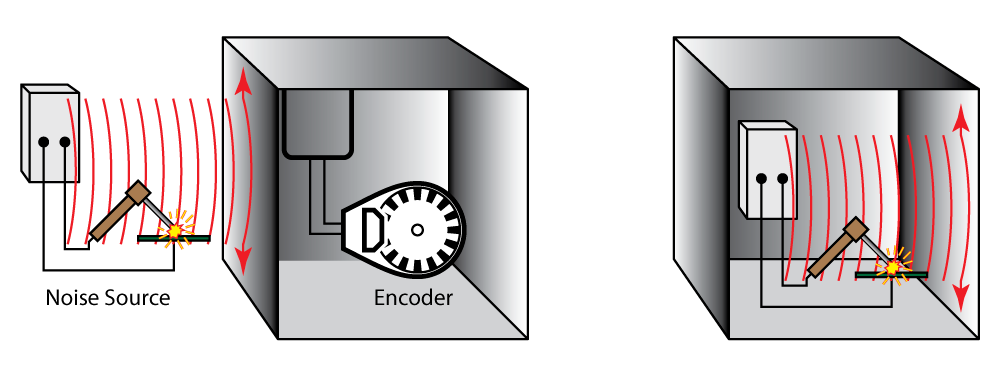
If sensitive equipment is placed inside a Faraday shield, the enclosure will keep that equipment from being bombarded by EMI. It also works in the other direction: if noisy equipment is placed inside a Faraday shield (think equipment cabinet), the EMI from the noisy equipment can’t escape to cause trouble for sensitive devices.
You can use cables and equipment that act like Faraday shields to help control EMI and electrical noise.
Shielded cables are available with shields made from metal foil, braided conductors, or a combination of both. Use shielded cables to keep EMI away from your sensitive encoder signal lines. You can also use shielded cables for your noisy equipment wiring—the shielding can keep EMI contained within the cable so it doesn’t cause problems elsewhere in the system.
Metal conduit can be a very effective shield. EMI from electrically noisy equipment can be contained when wiring is run inside conduit. If sensitive signal lines are placed inside their own conduit, the conduit can block EMI from interfering with the signal lines.
Metal equipment enclosures can provide a shield to keep EMI inside, so that it doesn’t interfere with external devices; or to keep EMI out, when sensitive equipment is located inside the shielded equipment cabinet.
Here are some tips for using shielding:
- Use shielded cables for sensitive signal lines, and for noisy equipment as well
- Use conduit when possible, especially for noisy power lines
- Use equipment cabinets made from conductive materials
In all of these cases, the shielding will work best if it is properly grounded.
Grounding can help mitigate impacts of EMI
Proper grounding can provide a low resistance path to ground, which leads EMI and electrical noise away from your equipment and dissipates it in the grounding system.
You can direct the path of unwanted noise and show it where to go by using good grounding techniques. One of the most important things to do is to connect the shield of the encoder cable to a single ground point.
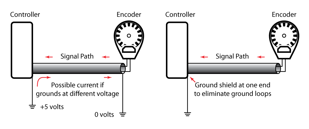
If you have multiple grounds in your system, theoretically they should all be at the same voltage. But in real systems, they may differ; if so, current can flow from one point to another—sometimes through your equipment, which can cause electrical noise and problems.
Here is a tip for grounding the shield of an encoder cable: Connect the encoder cable shield to ground at one end only, typically at the controller end.
Grounding is a complex topic, and affects everything from the power grid down to the smallest components in a microprocessor. If you spend some time to get it right for your system, good grounding will help diminish electrical noise problems.
Electrical noise happens but with these tips, you'll be ready
Electrical noise happens. It’s often impossible to eliminate it entirely, but it can be reduced. The techniques we’ve presented are a first line of defense; they can help lower noise to a level where it doesn’t cause problems for the signals from your encoder.
For serious electrical noise situations, there’s more that can be done, such as the use of filters, ferrite absorbers, conductive sprays, P-clips, capacitors, MOVs, surge suppressors, special grounding techniques and a host of other methods. Should those refinements be necessary in your system, we hope that as you investigate them, this post gives you an understanding of why they might work.
More in News
Stay up to date
Sign up for our newsletter to stay up to date with our product updates, blog posts, videos and white papers.