
US Digital Automates Production Process Using Robot and In-House Engineering Talent
New Miniature Encoder Disks Caused Production Difficulties for Operators
When US Digital introduced the E4T, a new, miniaturized optical encoder, the people who processed components during production—the system operators—faced difficulties. Previous methods that worked perfectly for larger encoders were too cumbersome to use with the new, smaller encoder disks.
To improve the operators' working conditions and free up their time for higher-level tasks, the company decided to automate a process that had always been done by hand. Because US Digital is a vertically integrated company with extensive engineering expertise and resources, it began working to solve the problem internally.
Developing a new automation system is never easy. There were occasional roadblocks along the way, but with perseverance US Digital designed an entirely new system, based on a delta robot, and achieved a successful outcome.

The Previous Method - Before Miniaturization
At the heart of a US Digital optical encoder is a transparent Mylar disk with a pattern of black lines on it. Operators produce the disks in US Digital's photo darkroom using high-precision photo plotters at resolutions up to 50,000 dpi. The Mylar film is developed in the darkroom, and then transferred via a conveyor system to the laser cutting room next door.
At the laser cutting table, the operators place the film on a backing sheet of paper. They set up the laser cutter to run, start the automated process, and then are free to do other tasks while the laser cuts out individual disks from the Mylar sheet.
The automated laser begins by using its vision system to locate fiducial marks, which are small crosshairs or unique marks printed on the film and used for alignment. Once it knows where the disks are located, the laser cuts a circle around each disk's outer diameter, and a smaller circle around an inner diameter, as well as specific features needed for the unique disk design. The heat of the laser slightly melts the edges of the disks, and they adhere to the backing sheet of paper underneath.
Operators return and move the sheet of disks to a worktable. In a manual process called 'disk picking', they pick the adhered disks from the sheet and stack them on a rod for storage in inventory.
A New Method - After Miniaturization
For years, disk picking had been an occasional minor task for the operators. It was something they could easily fit in during their busy workday and it didn't take much time—until a new product disrupted the status quo.

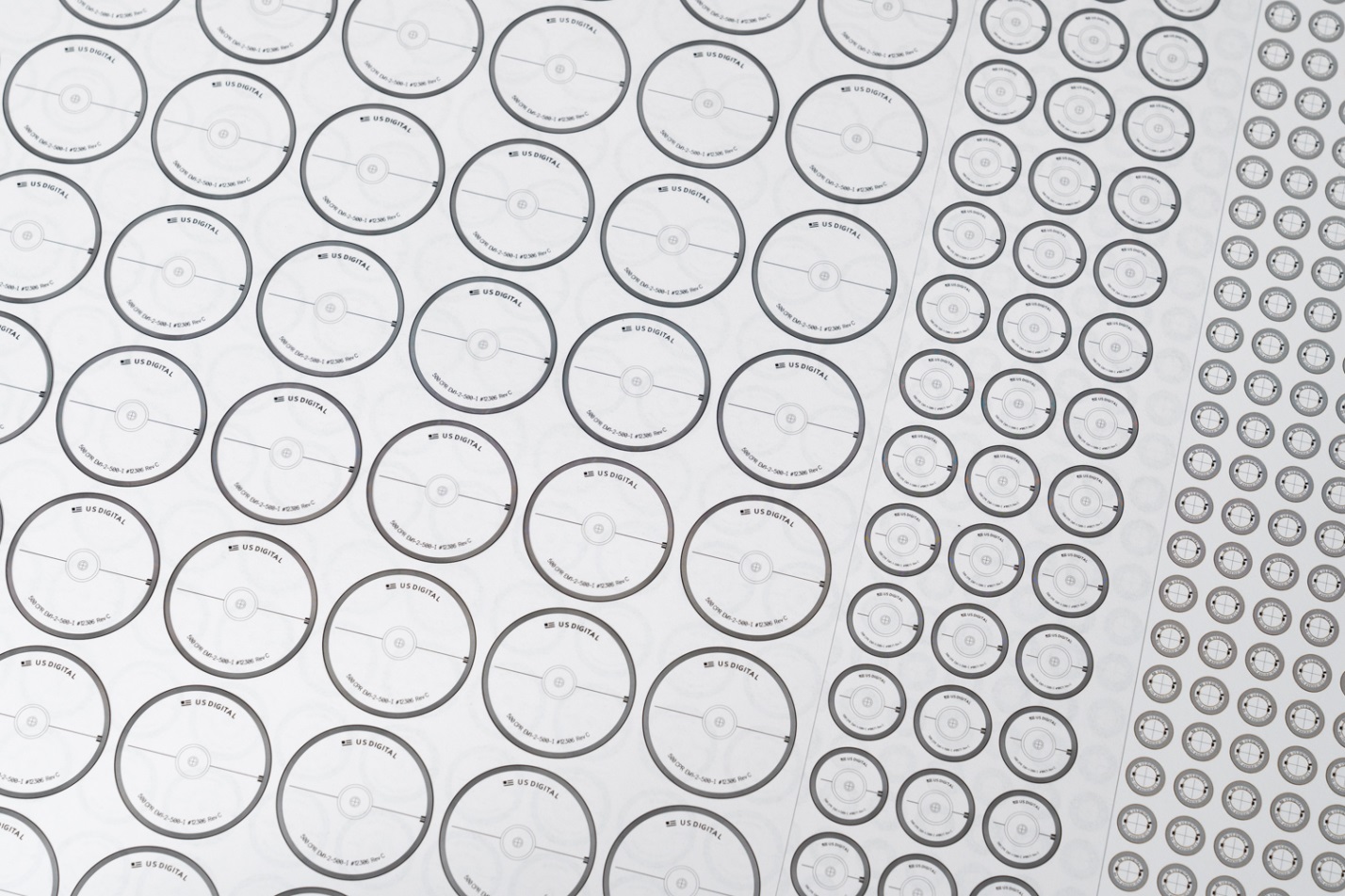
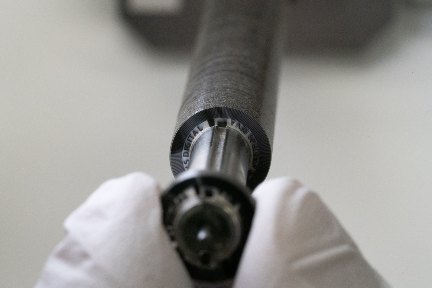
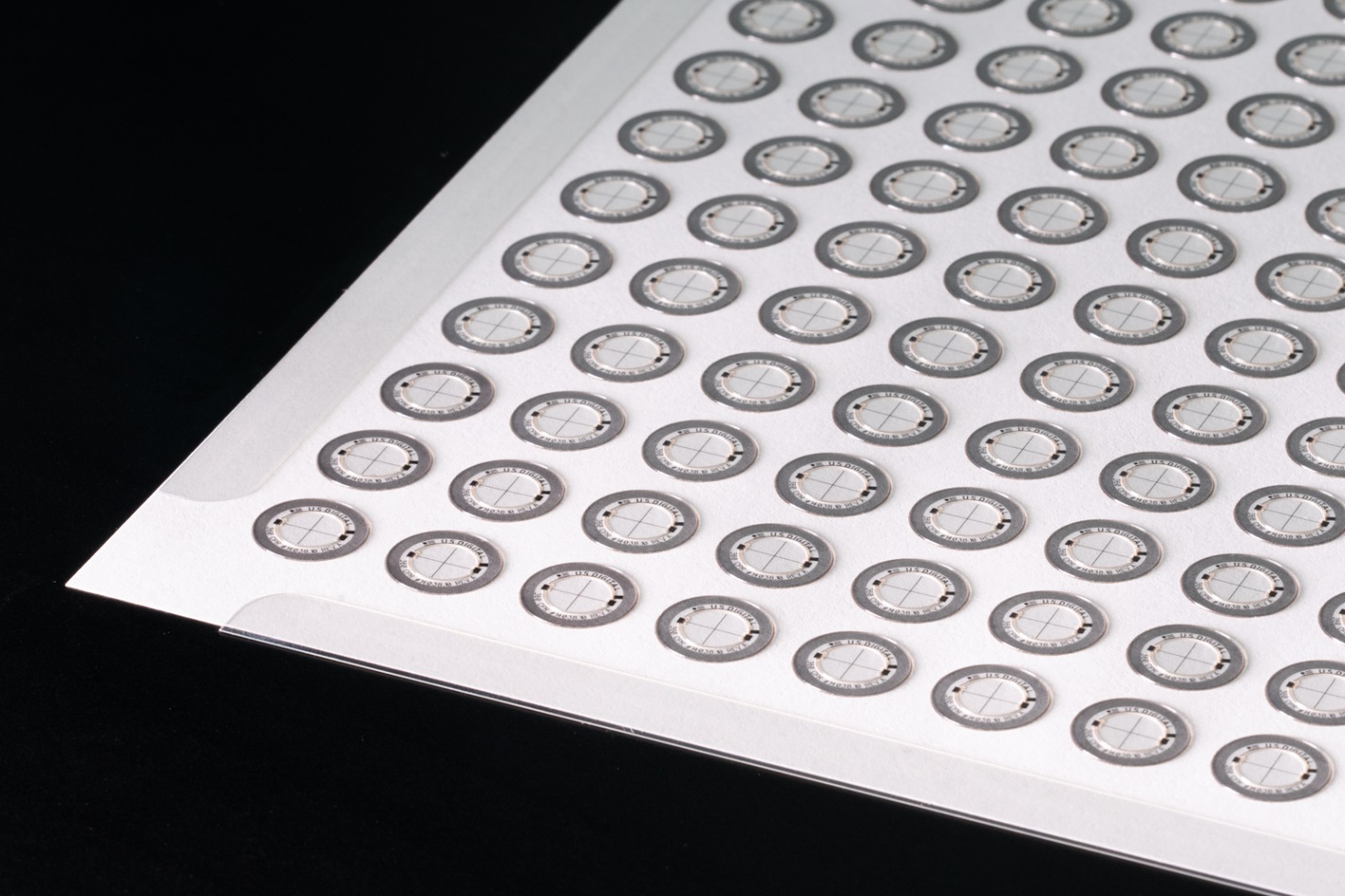
US Digital's E4T optical encoder was designed to satisfy the demand for miniaturized motion control products, used where space is limited. The Mylar disk for the E4T is only half an inch in diameter, roughly the size of a shirt button, though much thinner at seven thousandths of an inch.
E4T disks are produced in quantities of more than a thousand disks per sheet.
Their tiny size and large quantities made the new disks more difficult for the operators to pick, but there was an additional problem. On each disk, two tabs protrude into the space of the inner circle; these tabs align with grooves in the hub to which the disk mounts later in the assembly process.
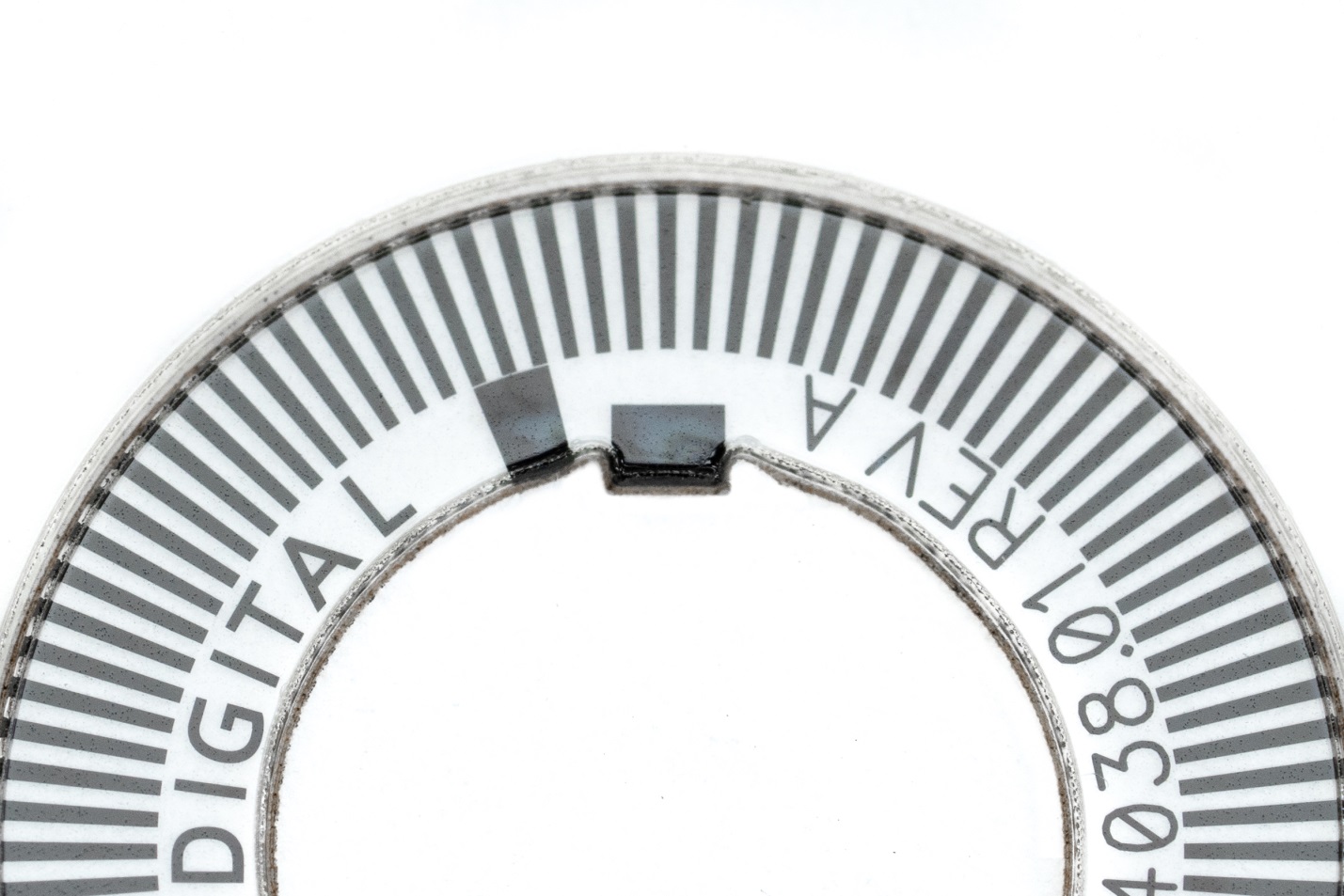
The operators had to precisely align the tabs on the new, smaller disks with grooves cut into the stacking rod—something that they never had to do with other encoder disks. The grooves helped prevent damage to the tabs while they were stored in inventory—but aligning the tabs with the grooves made it much harder for the operators to stack the disks.
"The E4T was really a problem, as far as picking them off and stacking them. It was a painful process," said Neal Donowitz, Chief Operating Officer at US Digital.
After the E4T was introduced to the market it became very popular. Sales grew rapidly, and the operators found that they were spending more and more time at the intensely laborious job of disk picking. They had less time for their other tasks in the darkroom and laser cutting room.
"We look for ways that machines can help our people, rather than having our people help machines," said Donowitz.
He thought the disk picking procedure could be updated and performed by an automated robotic machine. But rather than send the job out to be done by contractors, he followed the US Digital core value of vertical integration, and chose to do the development in-house. The robot would be a purchased part, but Donowitz knew that US Digital engineers, machinists and operators had the advanced skills to build everything else needed for the job.
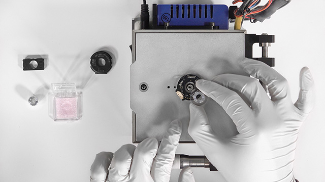
Kyle Viestenz, a mechanical engineer at US Digital, was tasked with heading the automation project. Viestenz saw that there was another benefit of using a robot for disk picking.
"We wouldn't be handling the disks as much," he said. "The operators use gloves, and they're really nimble and quick, but a half-inch outer diameter, seven thousandths of an inch thin—these are tiny little things that are easy to drop or bend. Building a machine would help take care of these types of issues."
But first, he had to find the best type of robot for the job.
Choosing a Robot
When Viestenz began considering options for a robot that could perform the disk picking job, he heard about delta robots from company founder and CEO David Madore.
"Delta robots are great, because all the heavy parts, like the motors, don't have to move through space," Madore said. "They're rigidly mounted to the top of a frame, and only the lightweight arms hang down."
Their other advantage, according to Madore? Unlike traditional assembly robots, which have to be beefed up to move the massive arms, motors and grippers, Delta robot arms have very little moving mass.
"They can accelerate quickly and move at high speeds. They're ideal for transferring lightweight loads very quickly," he said.

Viestenz decided on a delta robot.
"Its speed was the key," he said. "It was also within the accuracy we needed, and it had the workspace we wanted. A delta robot seemed like a good fit for this project."
Building a System around the Robot
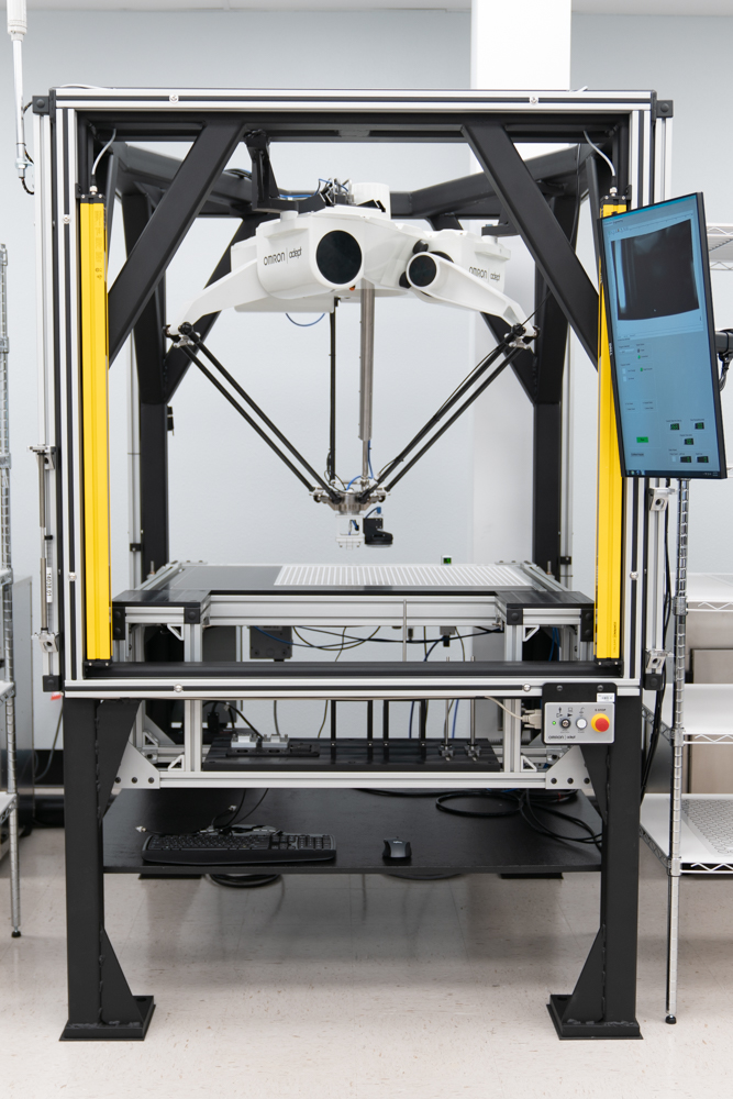
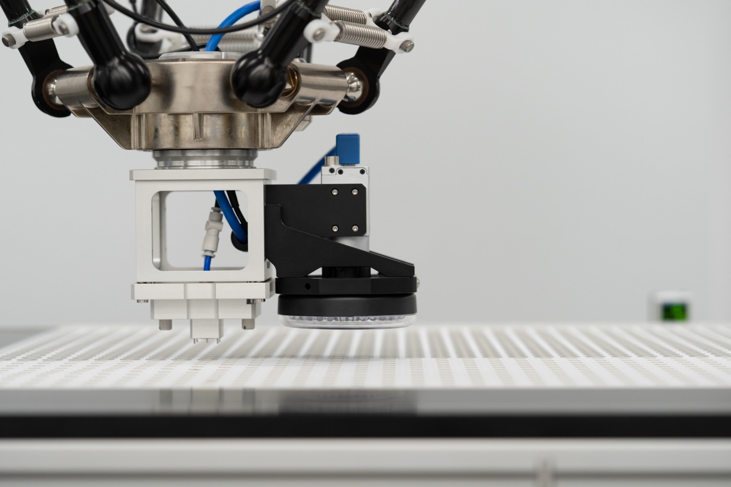
Selecting and purchasing a robot was only the beginning. The robot came as a unit, but it required a system to be built around it. Viestenz needed a frame to support the robot, a table to support the disks as the robot worked on them, tools to handle the disks, vacuum and forced air systems, a vision system and many other items. Everything in the next picture—except the robot—had to be designed and built.
It turned out Viestenz would need to solve many problems as he built a machine around the robot.
The Frame
Surrounding the entire system is an outer frame, 4.5 by 4.5 feet and 7 feet tall. The main frame members are made from 3-inch by 3-inch by 1/4-inch wall steel square tube, and the brackets are made from 1-inch thick steel plate.
The robot mounts inside the top of the frame, and a work surface is mounted halfway down, under the robot's arms. Viestenz tailored the design of his frame to accommodate the required workspace for disk picking.
The frame had to be very rigid. "You can really lose positioning accuracy if there's movement of the frame during robot motions," Viestenz said. "That's why the frame is so massive; it weighs just over 800 pounds—just the frame, without anything else."
The frame also had to fit into the room where it would be used. Viestenz designed it with 1/4 inch of clearance between the top of the frame and the doorway to the room.

At one point Viestenz considered having the frame built by outside suppliers, but ran into several problems with that approach. Vendor lead times were considerable. And the frame had to be square to a tight tolerance; otherwise, the robot would lose accuracy. When Jeff Conner, one of US Digital's skilled machinists with excellent welding skills looked at the plans, he said, "I can build that." He got the opportunity, and the frame he made turned out to be sturdy, rigid, square and delivered on time.
Eliminating Vibration
When Viestenz was developing the machine in US Digital's engineering test area, the frame stood on a concrete floor. He said that even with that massive frame, "When I put the machine together and ran it, it shook quite a lot; you could feel it vibrating." He knew he'd have to find a way to damp the vibrations. Whenever the machine made a fast move and then stopped, its final position needed to be accurate; any lingering vibrations could cause errors.
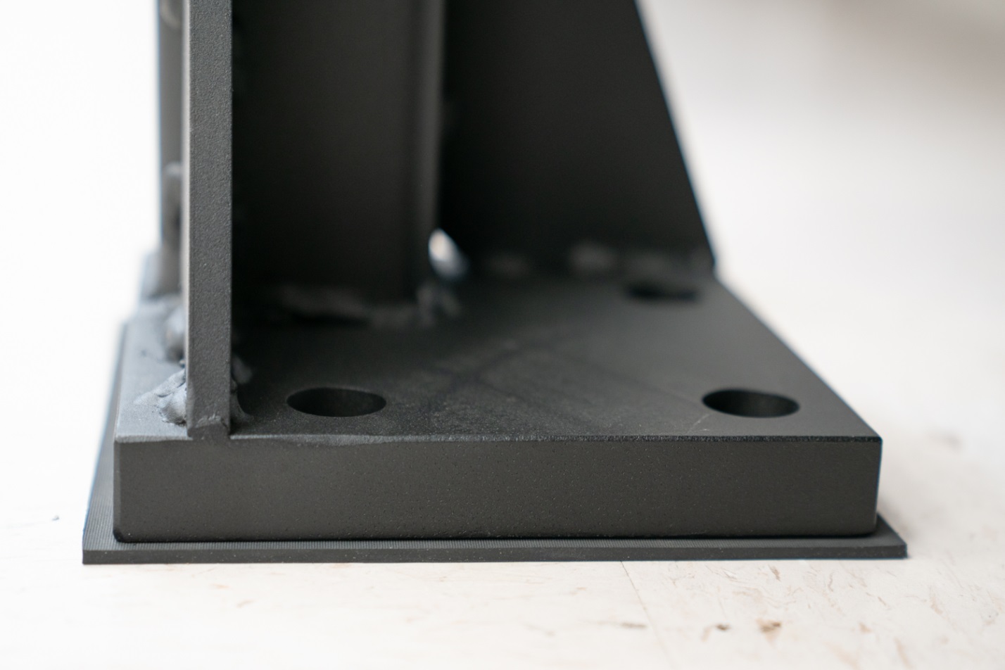
Viestenz found a simple solution. Rather than bolting the frame to the concrete floor, as is commonly done, he used vibration-isolating rubber padding under each foot. The padding did a good job of damping the structural vibrations of the frame. As an added benefit, Viestenz found that the padding compressed a bit under the weight of the frame, which helped smooth out unevenness in the floor.
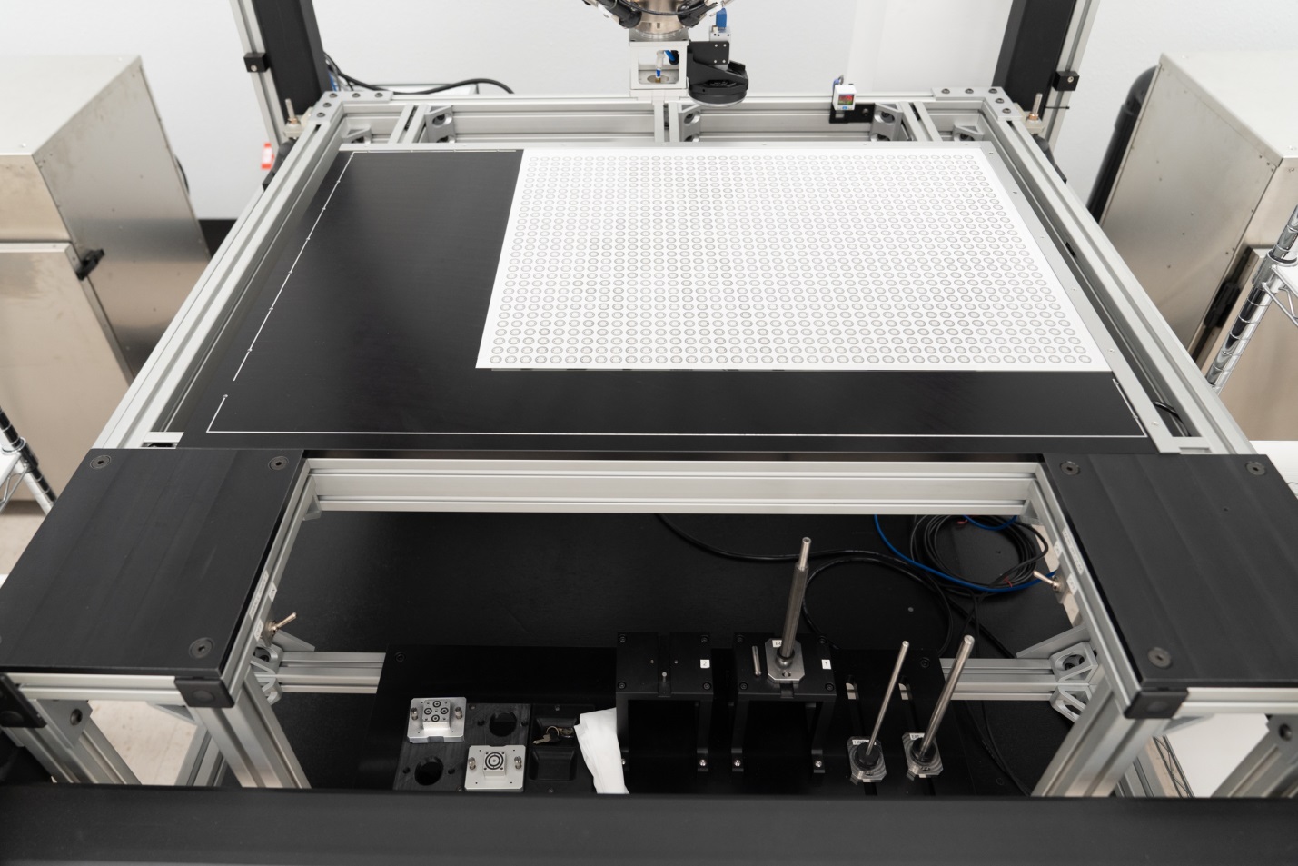
The Work Table
A work table is mounted inside the frame, 38 inches above the floor, where the sheet of paper with disks is placed.
Viestenz designed the table with adjusting bolts on its four corners. He can move each corner up and down as needed, to adjust height, pitch and roll independently of the frame. "I can effectively make the table parallel to the robot's horizontal plane of travel," Viestenz noted.
Vacuum Channel and 'Picture Frame' Hold-Down System
One of the challenges Viestenz faced was how to hold down the large sheet of backing paper while the robot picked disks from it. He first tried placing a vacuum channel in the work surface, under the perimeter of the paper; it's a machined groove with holes in it which are connected to a vacuum source. He found, however, "The paper is porous. When we tried to pull a vacuum on the paper, it wouldn't do anything—air would go right through the paper."
He came up with an ingenious solution. He made a 'picture frame' out of Mylar that fit around the edges of the paper, and rested above the vacuum holes in the channel. The Mylar created a seal around the vacuum channel, which successfully held the paper down.
The Vision System
At the start of each run, a camera mounted at the end of the robot's arm takes an image of the fiducial (location crosshair) at each corner of the sheet. "Originally I had the camera mounted high up on the frame. The camera was going to look down at a small portion of the sheet, to get the sheet oriented within the robot's coordinate system," Viestenz said. But he found that looking at only a small area and extrapolating positions for the rest of the sheet wasn't good enough. He had to know the skew of the sheet exactly. "I found I had to move the camera down to the end of the arm of the robot, and get a lot closer to the sheet. Then I could actually move around, grab locations of the fiducials anywhere on the sheet."
Once the camera takes images of the four corners at startup, the system computes the skew of the sheet, and orientation within the robot's coordinate system is complete.
The Tool
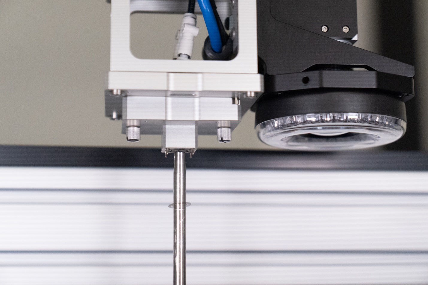
The robot does not use fingers or grippers to pick up disks. Instead, Viestenz designed a tool that attaches to the end of the robot's arm and uses a combination of vacuum channels and spring-loaded hold-down pins to pick up the disks; it uses compressed air to help release the disks.
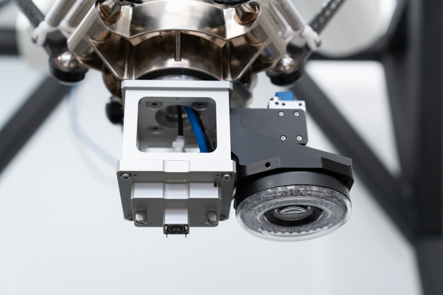
The tool is shaped like an elongated cube. O-rings are embedded in its bottom surface, with adjacent tiny vacuum channels. As the tool comes down, the O-rings create a good seal on the disk, and the vacuum channels deliver suction. Spring-loaded pins around the periphery of the tool push against the paper to hold it down as the tool presses against the disk, picks it up and begins to move away. The pins release from the paper after the tool has moved a fraction of an inch from the sheet.
"There's a spring-loaded pin in the middle, too," said Viestenz, "which helps us hold down the ID crosshair." It's helpful to leave the fiducial in place; that way, if the operators do part of a sheet and then stop, they can still locate the fiducial and re-orient the machine at a later time.
During development, Viestenz discovered that he had to account for small variations in flatness of the table, to get good alignment between the tool and the table for optimum suction. When the robot lowers the tool, it can only move up and down, and in the X-Y direction. Viestenz designed a spring-loaded plate to address this issue; the plate adjusts in the pitch and roll directions, via the springs. The tool previously mentioned is mounted to this spring-loaded plate.
Viestenz designed not just one, but a series of tools to accommodate the various disk sizes that US Digital makes. The tools were precisely machined in-house by US Digital machinists. Viestenz also designed a rack to hold the tools when they are not in use; it fits conveniently between the frame and work table.

"The system is flexible enough for new tools to be made and new programs to be written which can accommodate future products," Viestenz noted.
Stacking Rods
After picking up a disk, the robot moves at full speed to the edge of the table, where it stops and hovers above a vertical stacking rod.
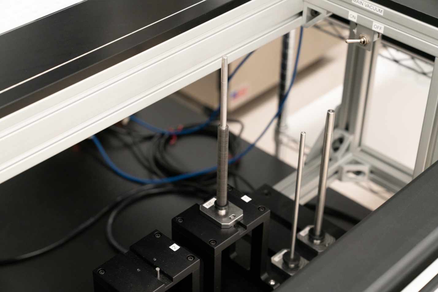
The vacuum turns off, and to help the disk on its way, a jet of compressed air blasts the disk off the tool and down the rod.
Viestenz designed a series of stacking rods for the various sizes of disk that are processed on the machine. For the rods used with E4T disks—the ones with the two tabs protruding into their internal diameter—he created matching grooves in the rods to accept the tabs. The robot precisely aligns the disk above the rod, so that the tabs line up perfectly with the grooves when the disk is discharged from the tool.
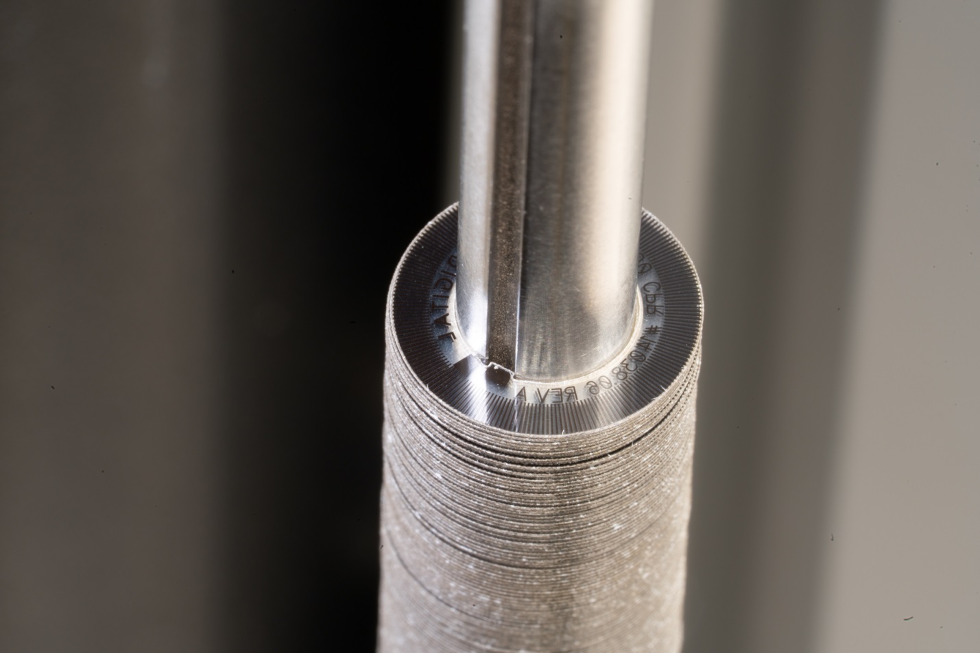
To allow for tolerances while discharging the disks, Viestenz designed a removable, tapered tip to fit on the end of the rod. This creates relief to account for position errors of up to 20 thousandths of an inch as the robot moves into position.
To keep the rods at a reasonable length, Viestenz created two stations—two rods stand side by side. When the robot processes E4T disks, it stacks 600 disks on one rod, and 600 on the other rod.
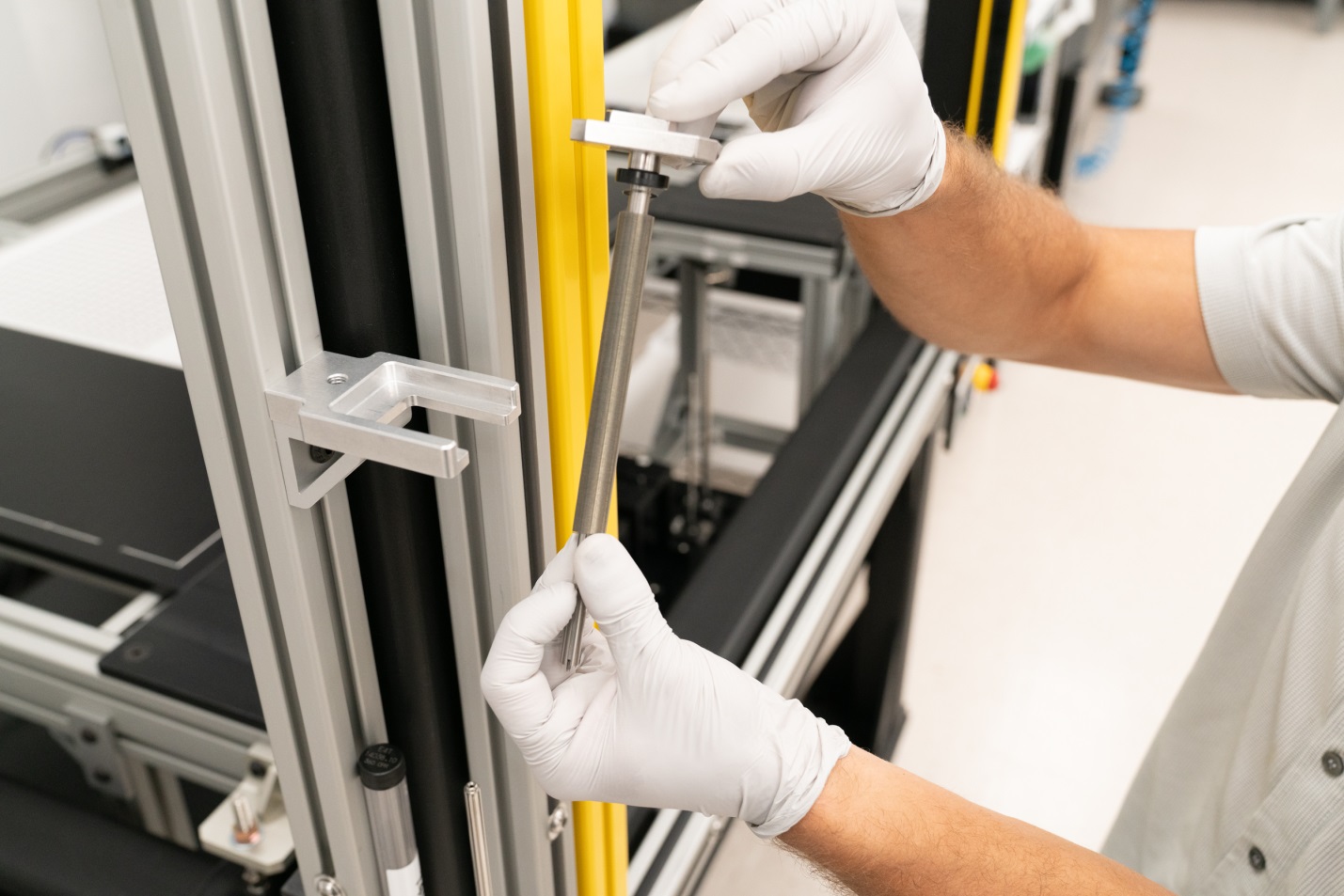
Transfer Station
Once a rod is full, the disks are transferred to another rod for transport and storage in the inventory area. Viestenz designed a transfer station where the operators can perform this delicate task. They remove the tapered end from the stacking rod, and insert it onto the end of the storage rod. It's then a simple task for the operator to slide the disks from one rod to the other.
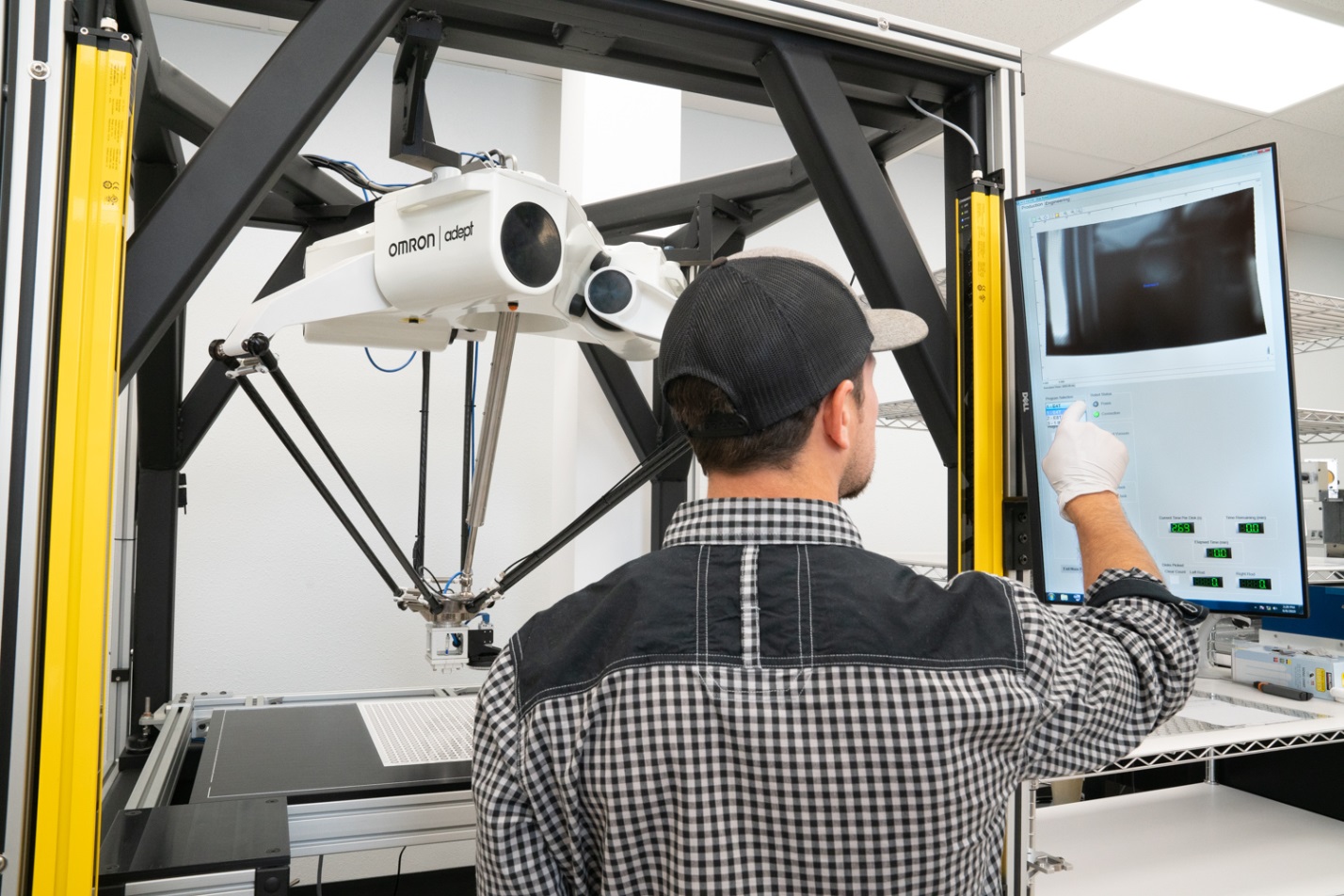
Human Machine Interface (HMI)
Viestenz designed the HMI to be intuitive and reliable. The interface is a large, touch-sensitive flat panel display, mounted to the frame at a convenient height. Operators can control machine functions by selecting menus and touching buttons on the screen. Viestenz said, "We tried to keep it simple, and usable as well. It keeps track of elapsed time, and how many disks have stacked up. It makes a rough prediction of how much longer it's going to take, and how long it's taking for each disk."
During development, operators Igor Korotin and Paul Fedorenko contributed to the design of the HMI, and Viestenz included many of the special functions they knew would be needed. Because the robot arms, high above, are equipped with absolute encoders, position information is retained if the operators need to stop midway through processing a sheet of disks. When resuming, the operators can choose to start in a different location, identified by row and column. They can also choose how many disks they want to pick up. "Most of the time, you'll pick a whole sheet," Viestenz explained, "but Igor and Paul knew these other options would be nice to have. I put them into the interface, to give them the flexibility."
Light Curtain for Safety
When the robot operates in high power mode, it moves very quickly. For the safety of the operators, Viestenz installed a light curtain in front of the machine. Multiple infrared beams create an invisible barrier; if someone moves too close and interrupts any of the beams, an emergency stop is triggered and the robot halts immediately. When ready, the operator can restart the robot from where it left off. No homing move is necessary, thanks to the absolute encoders that report the robot's tool position.
Discoveries During Development
As the parts came together and the machine began to take shape, Viestenz could begin to operate it—slowly at first, with motion limited to short moves, and then eventually at full speed while picking disks from an entire sheet. Much of the development went as planned, but he had to solve many unexpected problems along the way.
Motion Programming
When he programmed the machine for motion, Viestenz had to adjust speeds and accelerations. It took time to get everything just right. As the tool began lifting the disk from the sheet, he experimented with the tool's speed, searching for the right amount of time to get a good vacuum seal and not leave the disk behind. At the other end of travel, when the tool discharged the disk onto the rod, he adjusted speeds there for precision. He also put the robot through high speed motion, searching for the fastest possible velocity once the disk was picked off the sheet. His goal was to reduce total cycle time.
Rotation about the Vertical Axis for Positioning
Delta robots move up and down in the Z direction, and maintain orientation of the tool in the X-Y plane—the tool usually does not rotate about the vertical axis. At the start of the project, Viestenz realized that these three axes of motion would not be enough.
For this system, the tool had to drop the disks onto the stacking rod with their tabs precisely aligned with the matching grooves in the rod. If the sheet of disks was perfectly aligned and square in relation to the table, things worked perfectly. But Viestenz needed a way to allow for some skew in the sheet.
To compensate for skew, he ordered an optional 4th axis when he purchased the robot. A splined rod can extend in and out, and rotate the flange to which the tool is attached. This extra rotation about the vertical axis solved potential alignment problems by allowing the skew angle to be incorporated into the robot's coordinate system. Each disk's tabs could now be positioned correctly above the grooves in the stacking rod.
Some Disks Wouldn't Release from the Backing Sheet
Occasionally a disk adhered so tightly to the backing sheet that the robot couldn't pick it up. Viestenz had to find a way to determine when this happened, and instruct the robot what to do in that event.
He installed a sensor and programmed it to check vacuum pressure after each disk was picked up. If the reading wasn't above a certain level, it indicated that the disk had been left behind. In that case, "It will try one more time," Viestenz said, "and if the second attempt fails, the robot moves on to the next disk." The stuck disk remains behind on the paper.
Aerodynamics and Disk Diameter
The most efficient way for disks to stack is for them to leave the tool face quickly, and rapidly shoot down to the bottom end of the stacking rod. If they were to float down slowly, there is a chance they could hang up on the rod before reaching bottom, and potentially cause a jam as more disks arrive. The machine is designed to run unattended, so jams and overflowing disks are unacceptable.
Viestenz used a quick burst of compressed air to push the disk from the tool and onto the stacking rod, in what is called a 'blow off' procedure. "I thought the smallest disks like the E4T were going to be the tougher ones," Viestenz recalled. "But for them, the blow off works really well—it just shoots it down to the bottom, you can't even see the disk, it moves so fast."
The larger 1-inch disks caused problems. They dropped more slowly, perhaps because their larger diameter caused increased air drag. When Viestenz tried increasing the air pressure to get the disk to move downward faster, he was surprised to find that the additional air caused the disks to stick to the face of the tool, and not release quickly enough. It seemed the fast-moving air and the larger disk diameter combined to create a slight vacuum suction between the disk and the tool. Getting it right turned out to be a delicate balancing act.
Success!
One by one, Viestenz solved each problem as it came up. Development is now done, integration of all the parts is complete, and the disk picking machine is working away in the production area. It's accomplishing all the goals that Viestenz and Donowitz outlined at the beginning of the project.
Donowitz concludes, "We use the robot to help people, and let the people go off and do the higher level work. They can do all kinds of other tasks, at the same time the machine is running. It's efficient in that way."
Instead of laboriously picking and stacking the disks themselves, the operators can now set up the machine, push a button, and let the robot perform the entire process.
More in News
Stay up to date
Sign up for our newsletter to stay up to date with our product updates, blog posts, videos and white papers.