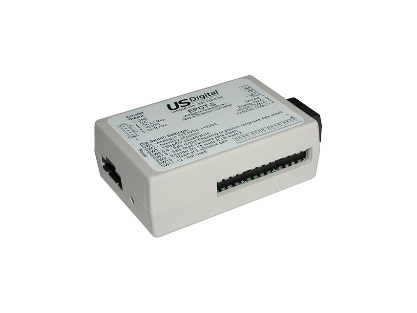
Note: After changing the DIP switch settings, the EPOT must be power cycled to ensure that the device configuration is updated.
DIP switch 1:
Selects the maximum analog input voltage. This voltage must match the output voltage used on connector J1.
↑ Up (1) position for +3.6V max. analog input
↓ Down (0) position for +5V max. analog input.
DIP switch 2:
Selects either velocity output mode or position output mode.
↑ Up (1) position for velocity output mode.
↓ Down (0) position for position output mode.
DIP switch 3:
Selects either quadrature output mode or step/direction mode.
↑ Up (1) position for step/direction output mode.
↓ Down (0) position for quadrature output mode.
DIP switches 4, 5 and 6:
Select the output frequency (for velocity output mode) or position range (for position output mode) as shown in the tables below.
| SW4 |
SW5 |
SW6 |
POSITION OUTPUT MODE |
VELOCITY OUTPUT MODE |
| ↓ |
↓ |
↓ |
-15 to 15 counts |
4.1KHz CCW to 4.1KHz CW |
| ↑ |
↓ |
↓ |
-31 to 31 counts |
8.3KHz CCW to 8.3KHz CW |
| ↓ |
↑ |
↓ |
-63 to 63 counts |
16.6KHz CCW to 16.6KHz CW |
| ↑ |
↑ |
↓ |
-127 to 127 counts |
25.0KHz CCW to 25.0KHz CW |
| ↓ |
↓ |
↑ |
-255 to 255 counts |
33.3KHz CCW to 33.3KHz CW |
| ↑ |
↓ |
↑ |
-511 to 511 counts |
50.0KHz CCW to 50.0KHz CW |
| ↓ |
↑ |
↑ |
-1023 to 1023 counts |
66.6KHz CCW to 66.6KHz CW |
| ↑ |
↑ |
↑ |
-2047 to 2047 counts |
100.0KHz CCW to 100.0KHz CW |
DIP switches 7 and 8:
Selects the size of the dead band. The dead band is a selectable zero velocity output range. With human interface applications utilizing potentiometers or joysticks, it is difficult to return to a very precise zero velocity output location. A wider dead band makes it much easier to return a potentiometer or joystick to a zero-velocity point. This adjusts the width of the zero velocity dead band in the center of a potentiometer or joystick.
| SW7 |
SW8 |
DEAD BAND |
| ↓ |
↓ |
0% (no dead band) |
| ↑ |
↓ |
2% |
| ↓ |
↑ |
4% |
| ↑ |
↑ |
6% |
DIP switch 9:
Selects the encoder output direction. Moving this switch to the opposite state will change the direction output of the encoder signals.
↑ Up (1) position for normal direction on A and B.
↓ Down (0) position for reverse direction on A and B.
DIP switch 10:
Selects between a standard potentiometer and joystick style potentiometer. The typical total rotation seen by a potentiometer-based joystick is about 50 degrees. This switch adds a gain of 5 to enable the limited travel of a joystick potentiometer to produce a full-scale output from the EPOT. If a standard potentiometer is used with the EPOT, the gain should be disabled. If the gain is not disabled, the EPOT will reach a maximum value over about a 50-degree rotation of a standard potentiometer.
↑ Up (1) position to increase input gain by a factor of 5.
↓ Down (0) position to disable the gain increase.
DIP switch 11:
Selects which application is being used: potentiometer or joystick.
↑ Up (1) position for potentiometer applications.
↓ Down (0) position for joystick applications.
DIP switch 11 is only active when the EPOT is set up in velocity output mode. This switch determines how the EPOT will detect the zero-velocity position of the potentiometer or joystick attached to its analog input. The Up (1) position will calculate a midpoint location which provides zero velocity output when power is applied. The Down (0) position will assume the potentiometer or joystick is located in its midpoint or zero velocity position when power is applied


