US Digital will be closed on Thurs., Nov. 28, and Fri., Nov. 29 in observance of the Thanksgiving Holiday. We will reopen Mon., Dec. 2 at 6:30 AM PST.

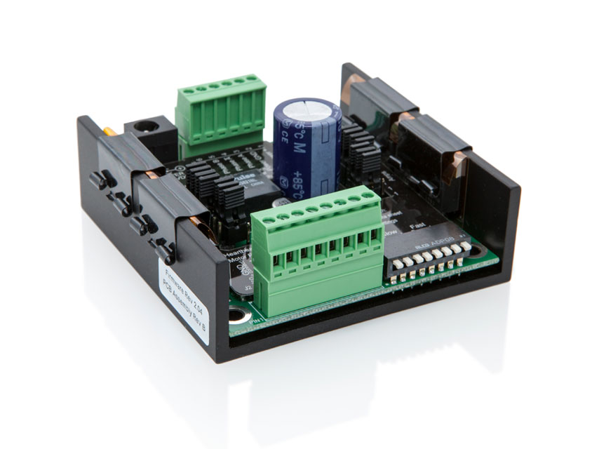
MD2S MICROSTEPPING MOTOR DRIVER

MD2S Features

  • 31 microstepping resolutions from 2 to 256 microsteps per step
  • 0.5 to 7.0 amps peak per phase current in 0.5 amp increments
  • Low current option: 0.20 to 3.6 amps per phase current in 0.05 amp increments
  • Single +16 to +50V supply voltage
  • Isolated inputs
  • LED indicators
  • Drives size 17 to 42 stepper motors
  • Silent and efficient, recirculates motor current
  • Anti-resonance algorithm insures smooth, quiet operation
  • No trimming or adjustments needed

See more info below

Configure the MD2S

The MD2S is no longer available for purchase.

MD2S Product Description

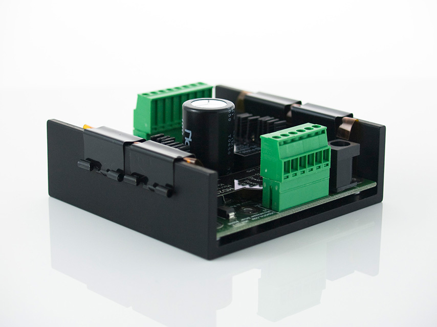
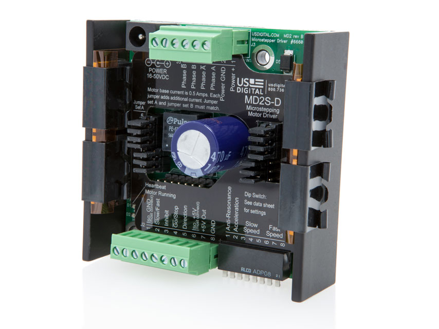
The MD2S is a universal programmable microstepping (stepper) motor driver capable of driving size 17 to 42 stepper motors. Peak motor currents are selectable from 0.5 to 7.0 Amps per winding in 0.5 Amp increments. The L-option (low current) is selectable from 0.20 to 3.6 Amps per winding in 0.05 Amp increments. The MD2S is powered by a single supply voltage from +16 to +50VDC.

The MD2S-D is a digital speed control version of the MD2S. This version provides a practical method to spin a stepper motor without the need for a motor controller. 4 digital inputs and 8 DIP switches provide the ability to ramp up and down, run slow or fast, and reverse directions.

Conventional drivers use a pump-up / pump-down PWM cycle that generates undesirable ripple current and eddy current losses. In contrast, the MD2S uses a more efficient pump-up / recirculate modified PWM cycle that significantly reduces this power loss and the resulting heat. This is most noticeable when the motor is at or near zero speed.

Product Specifications

MECHANICAL

Weight 5.7 oz. (with mating connectors)
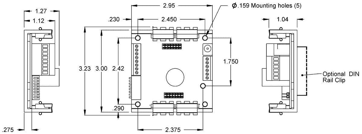
Size 2.95" x 3.23" x 1.27"
Mounting Pattern Use 2 to 5 - #4 or #6 machine screws
Case Material Black anodized aluminum
Operating Temperature 0C to 70C

ELECTRICAL

PARAMETER MIN. MAX. UNITS
Input Supply Voltage +16 +50 VDC
Input Supply Current* 0.05 2.5 Amps
Isolator Supply Voltage +4.5 +5.5 VDC
Isolator Supply Current 2.0 25 mA
+5VDC Power Out Voltage 4.75 5.25 VDC
+5VDC Power Out Current - 100 mA
Output Phase Current (selectable) - D-option 0.5 7.0 Amps
Output Phase Current (selectable) - L-option 0.2 3.6 Amps
Auto Current Reduction** 50 - %
Step Frequency 0 2.0 MHz
Logic Low Input Voltage*** -0.7 0.8 Volts
Logic High Input Voltage*** 2.0 5.7 Volts
Logic Low Input Current - 1.0 mA
Logic High Input Current - 1.0 mA

* For motor current settings of 4 Amps or less.
** Depending on setting of DIP switch 3.
*** Diode clamped.

MOUNTING

The MD2S package consists of a 0.125" thick anodized aluminum extrusion. Use 2 or more screws in any of the five 0.159" diameter mounting holes. Typical mounting screw sizes are #4 or #6.

J1 & J3 CONNECTORS

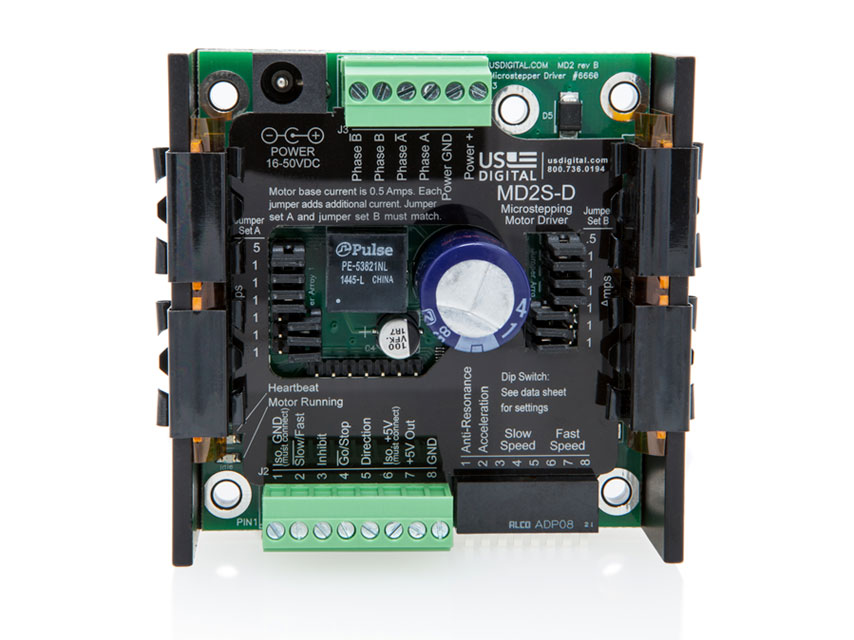
The MD2S has two pluggable screw terminal connectors and a power jack. The MD2S motor power may be applied to the J1 power jack or to the J3 6-pin connector. Plugging or unplugging the motor connector during operation will not damage the MD2S. Make sure that the terminal blocks are wired to the MD2S correctly before applying power. Do not allow the motor leads to short each other, to ground or to power as this could damage the MD2S.

J1 PIN-OUT:

Center Pin Motor power +16 or +50V (connected internally to J3 pin 1)
Barrel Main power ground (connected internally to J3 pin 2)

J3 PIN-OUT:

Pin 1 Power supply input (+16 to +50VDC)
Pin 2 Power supply ground
Pin 3 Motor winding A
Pin 4 Motor winding A-
Pin 5 Motor winding B
Pin 6 Motor winding B-

J2 CONNECTOR

All logic inputs are pulled high by internal 4.99 kOhm resistors to the isolated +5V source. Unused inputs may be left unconnected and are internally pulled up to their de-asserted state. Each input has a transient voltage suppressor that prevents the inputs from going more negative than -0.7V or more positive than +5.7V relative to J2 pin 1. All inputs cause a real-time response and are non-latching.

PIN 1 - ISOLATOR GROUND INPUT (NOTICE: THIS INPUT MUST BE CONNECTED)

This input supplies the ground return for power to the digital isolator.

PIN 2 - MD2S-P (STEP / DIRECTION VERSION) - REDUCE CURRENT INPUT

Pulling this input low reduces the motor current by 75% so that 25% remains. This allows the user to slowly move to a hard stop and stall, thus executing a home cycle without the need for a home position sensor. The red LED will turn on when this input is asserted. Asserting this input has priority over the zero-speed auto current reduction enabled by DIP switch 3 and is not additive.

PIN 2 - MD2S-D (DIGITAL SPEED CONTROL VERSION) - SLOW / FAST INPUT

Pulling this input low selects the slow speed set by DIP switches 3, 4 and 5. The high state selects the high speed set by DIP switches 6,7 and 8.

PIN 3 - INHIBIT INPUT

This input may be used as an emergency stop. Asserting this input (pulling this input low) will immediately cut the motor current to zero for all MD2S versions. All power MOSFET transitions are off; consequently, the motor windings are disconnected electrically from the circuit and the motor can rotate freely.

Please note that the MD2S-D will immediately stop without ramping down when this input is asserted. Deasserting this input (changing from low to high) will immediately restore motor current. The MD2S-D will then ramp up from zero speed to the selected speed at the selected acceleration if enabled.

PIN 4 - MD2S-P (STEP / DIRECTION VERSION) - STEP INPUT

The step input is digitally filtered and will not pass any pulses shorter than 150 nsec. Valid rates are from zero to 2 million steps per second. Either the rising or falling edge will cause the MD2S to step depending on the setting of DIP switch 2.

PIN 4 - MD2S-D (DIGITAL SPEED CONTROL VERSION) - GO / STOP

When this input is pulled low, the motor will ramp up to the selected speed. The high state will ramp down to stop. No time constraints are placed on this or the Direction Input of the Digital Speed Control Version. The MD2S will ramp up or down to follow the real-time inputs.

PIN 5 - MD2S-P (STEP / DIRECTION VERSION) - DIRECTION INPUT

The direction input should change no later than 90 nsec after the selected edge of the associated step input. The MD2S will accept either step and direction inputs or quadrature inputs (such as provided by an incremental encoder). The motor direction may be reversed by swapping pins 5 and 6 of J3.

PIN 5 - MD2S-D (DIGITAL SPEED CONTROL VERSION) - DIRECTION INPUT

This input controls the direction of the motor. If the motor is already running and this input is changed, the motor will ramp down to stop, then ramp up in the new direction. This input can be changed at any time and will cause the motor to ramp toward the desired direction. The motor direction can also be reversed by swapping pins 5 and 6 of J3.

PIN 6 - ISOLATOR +5V POWER INPUT (NOTICE: THIS INPUT MUST BE CONNECTED)

This input supplies power to the digital isolator.

PIN 7 - +5V POWER OUTPUT (NOT ISOLATED)

Normally, +5V and ground are provided by the user to supply power to the digital isolator. If external +5V power is not available, the user may jumper pin 6 to pin 7 and pin 8 to pin 1 so that the MD2S will supply power to the digital isolator.

This +5V output may be used to supply external circuits up to 100mA. Note that using pins 7 and 8 means that the inputs will not be isolated. This will usually not cause noise problems, but depends on the system grounding situation.

PIN 8 - GROUND OUTPUT (NOT ISOLATED)

Pins 7 and 8 are normally not used but if the +5V power on pin 7 is used, this will be the ground return. It is connected internally to the ground of the power jack and pin 2 of J3. Do not use this pin for motor power ground return.

DIP SWITCH SETTINGS

The 8 DIP switches may be changed while operating and changes take effect immediately without the need for a power-down cycle. The default position for all DIP switches is up. The speed or the direction of the MD2S-D can be changed on-the-fly by:

1) Changing the position of the speed select DIP switches.
2) Changing the Go / Stop input.
3) Changing the Slow / Fast input.
4) Changing the Direction input.

The MD2S-D will ramp to the new speed based on Fast / Slow acceleration determined by bit 2 of the DIP switch.

MD2S-P (Step / Direction Version) / MD2S-D (Digital Speed Control Version) DIP Switch Settings for SW1:

SWITCH 1 - ANTI-RESONANCE ENABLE

Up = Disable
Down = Enable

The stator of nearly all stepper motors have 50 magnetic teeth, 25 per winding, interleaved, and a permanent magnet rotor with matching alternating teeth. Applying current to the windings will generate attractive and repulsive forces to align the teeth of the stator and rotor. A four step quadrature sequence that applies full current in alternating polarities to each winding will step the motor through 1/50 of a revolution, resulting in 200 full steps per revolution. Switching the magnetic field in full steps from one extreme to the other causes the rotor to jerk, producing obvious noise and vibration. The rotor will ring by alternately leading, then lagging the commanded angle. The resonance frequency is dependent on the size and weight of the rotor. When full stepping, the resonance of a stepper motor is so pronounced that the motor will commonly stall even when no load is present.

Microstepping executes the same sequence but in smaller increments (sine and cosine) and solves the primary resonance problem. The finer the increments (resolution), the smoother, quieter and finer the movements. This same low frequency resonance can still be excited and will progressively build when spinning at higher speeds or when microsteps occur at frequencies related to the resonant frequency (typically around 210 Hz). It sounds like low frequency growling. The MD2S can sense and cancel this resonance to maintain smooth quiet high speed torque when enabled by DIP switch 1.

MD2S-P (Step / Direction Version) / DIP Switch Settings for SW2 to SW8:

SWITCH 2 -

Up = Step on Falling Edge
Down = Step on Rising Edge

SWITCH 3 - ZERO SPEED CURRENT REDUCTION

Up = Disable
Down = Enable

When enabled, the MD2S will automatically reduce motor current by 50% when step pulses have not occurred for at least one second. This will save power and allow the motor to cool between moves.

The motor position may change slightly when current reduction kicks in. Therefore, the current reduction feature should be disabled if the resting position of the motor must be accurately maintained. If this current reduction kicks in, the MD2S will turn on the red LED. Asserting J2 pin-2 (Reduce Current input) has priority and is not additive.

SWITCHES 8 TO 4 - RESOLUTION

These 5 DIP switches are used to select one of 31 microstepping resolutions from 2 to 256 microsteps per step. See the resolution table for a map. The higher the resolution, the smoother and quieter the motor. Special resolutions may be available upon request. See below for Microstep Resolution Table.

Decimal
Code
Hex
Code
Microsteps
per Step
Microsteps
per Rev.
16
SW4
8
SW5
4
SW6
2
SW7
1
SW8
29 1D 2* 400
30 1E 4* 800
0 00 5 1000
1 01 6 1200
2 02 8 1600
3 03 9 1800
4 04 10 2000
5 05 12 2400
6 06 15 3000
7 07 16 3200
8 08 18 3600
9 09 20 4000
10 0A 24 4800
11 0B 25 5000
12 0C 30 6000
13 0D 32 6400
14 0E 36 7200
15 0F 40 8000
16 10 48 9600
17 11 50 10000
18 12 60 12000
19 13 64 12800
20 14 80 16000
21 15 100 20000
22 16 120 24000
23 17 125 25000
24 18 128 25600
25 19 200 40000
26 1A 240 48000
27 1B 250 50000
28 1C 256 51200
29 1D 2* 400
30 1E 4* 800
31 1F 256 51200

*These resolutions are available with firmware revision 2.05 or later.

Please note: Special resolutions may be available upon request.

MD2S-D (Digital Speed Control Version) / DIP Switch Settings for SW2 to SW8:

SWITCH 2 -

Up = Enable Fast Acceleration
Down = Disable Fast Acceleration

Fast acceleration is factory set to 250 milliseconds per 1000 RPM. Slow acceleration is factory set to 500 milliseconds per 1000 RPM. The acceleration may also be customer specified.

SWITCHES 3, 4 & 5 - SLOW SPEEDS

These 3 switches are used to select one of 8 slow speeds. When J2 pin 2 is pulled low, the motor will ramp to the speed selected by these 3 switches. The standard speed choices are shown in the table below. These switches may be switched at any time. The MD2S will ramp up or down to follow the real-time setting of the switches. Other speed choices may be customer specified upon request by contacting a US Digital application engineer.

Code RPM RPS 2
SW3
1
SW4
0
SW5
0 4 0.07
1 10 0.17
2 25 0.42
3 50 0.83
4 100 1.67
5 200 3.33
6 300 5.00
7 360 6.00

SWITCHES 6, 7 & 8 - FAST SPEEDS

These 3 switches are used to select one of 8 fast speeds. When J2 pin 2 is high, the motor will ramp to the speed selected by these 3 switches. The standard speed choices are shown in the table below. These switches may be switched at any time. The MD2S will ramp up or down to follow the real-time setting of the switches. Other speed choices may be customer specified upon request by contacting a US Digital application engineer.

Code RPM RPS 2
SW6
1
SW7
0
SW8
0 480 8
1 600 10
2 720 12
3 900 15
4 1200 20
5 1500 25
6 1800 30
7 2100 35

LEDS

MD2S-P (Step / Direction Version):

The green LED flashes twice per second to indicate that the driver is powered on and working. The red LED is normally off. It turns on when the automatic current reduction kicks in (enabled by DIP switch 3) or if the reduce current input is asserted (J2 pin 2).

MD2S-D (Digital Speed Control Version):

The green LED flashes twice per second to indicate that the driver is powered on and working. The red LED is turned on when the motor is stepping and off when the motor is stopped.

POWER SUPPLY CURRENT

Nearly all of the power is consumed by the motor. The MD2S typically draws 50mA quiescent current. The current drawn from the power supply is normally much less than the current flowing in the motor due to efficient switching into the low motor impedance.

A 2.5 Amp power supply is sufficient for most applications where motor current is set to 4.0 Amps or less. Higher current power supplies may be required for higher motor currents, especially when high torque at high speed is necessary.

POWER DISSIPATION

The MD2S can safely dissipate a sufficient amount of heat in free air for phase currents less than 4.5 Amps. For 4.5 Amps or more, the bottom surface of the MD2S should be securely mounted on a heat sinking metal surface. Maximum continuous case temperature of the MD2S is 70C (158F).

Be sure that the motor screw terminal connections on J3 are tight. Loose connections may cause excessive heating at the connector as the MD2S tries to maintain the phase currents at the specified levels.

POWER SUPPLY VOLTAGE

High performance stepper motors are designed with minimum winding resistance and inductance to minimize heat loss and maximize high speed torque. Motor torque at low speeds is directly proportional to the current set by the MD2S jumpers and is not affected by power supply voltage or microstepping resolution. Torque remains relatively constant until it starts falling off at a speed threshold proportional to the power supply voltage.

The MD2S will operate from a single power supply voltage of +16 to +50VDC and has an internal transient voltage protector that starts conducting at 51V. Our PS-24 (+24V power supply) is recommended for most applications where motor currents are less than 4.5 Amps. Our PS-48 (+48V power supply) is recommended when maximum speed is desired.

MOTOR CURRENT JUMPERS

Each jumper set should have the same combination of jumpers and may be changed while the motor is operating. Care must be taken not to short other components. Hang onto the jumper handles with fingers or needle nose pliers while changing. Jumpers not in use may be plugged in so that only one pin makes contact, this will disconnect the jumper yet retain it for future use. The original jumpers provided with the MD2S should be used since they provide better connections for carrying motor current than other common jumpers. The single row of pins near the center of the MD2S are for factory use only. They are not for jumpers or customer use.

Standard Current:

Two sets of jumpers select the desired peak motor current, one for each motor winding. Set them to identical settings so that the motor phase currents are balanced. 0.5 Amp is the minimum recommended current. Base current is 0.5 Amp. Jumper 1 adds 0.5 Amp. Jumpers 2 to 7 each add 1 Amp. See chart below for more information.

Examples:

For 2.5 Amps, use jumpers 2 and 3: Base current (0.5) + jumper 2 (1.0) + jumper 3 (1.0) = 2.5 Amps.
For 4.0 Amps, use jumpers 1 to 4: Base current (0.5) + jumper 1 (0.5) + jumper 2 (1.0) + jumper 3 (1.0) + jumper 4 (1.0) = 4.5 Amps.
DESIRED PEAK CURRENT (AMPS) JUMPER 1 INSTALLED NUMBER OF JUMPERS 2 TO 7 INSTALLED
0.5 No 0
1.0 Yes 0
1.5 No 1
2.0 Yes 1
2.5 No 2
3.0 Yes 2
3.5 No 3
4.0 Yes 3
4.5 No 4
5.0 Yes 4
5.5 No 5
6.0 Yes 5
6.5 No 6
7.0 Yes 6

L-option (Low Current):

Two sets of jumpers select the desired peak motor current, one for each motor winding. Set them to identical settings so that the motor phase currents are balanced. 0.20 Amp is the minimum recommended current. Base current is 0.05 Amp. Jumper 1 adds 0.05 Amp, Jumper 2 adds 0.10 Amp, Jumper 3 adds 0.20 Amp, Jumper 4 adds 0.40 Amp, Jumper 5 adds 0.80 Amp, Jumpers 6 and 7 each add 1 Amp. See chart below for more information.

Examples:

For 0.35 Amp, use jumpers 2 and 3: Base current (0.05) + jumper 2 (0.10) + jumper 3 (0.20) = 0.35 Amp.
For 0.90 Amp, use jumpers 1 and 5: Base current (0.05) + jumper 1 (0.05) + jumper 5 (0.80) = 0.90 Amp.
For 3.50 Amps, use jumpers 1, 4, 6 and 7: Base current (0.05) + jumper 1 (0.05) + jumper 4 (0.40) + jumper 6 (1.00) + jumper 7 (1.00) = 3.50 Amps.

Please note: The chart below shows only Jumpers 1 to 5. Jumpers 6 and 7 will add 1.00 Amp each.

DESIRED PEAK CURRENT (AMPS) JUMPER 1 INSTALLED (ADDS 0.05 AMP) JUMPER 2 INSTALLED (ADDS 0.10 AMP) JUMPER 3 INSTALLED (ADDS 0.20 AMP) JUMPER 4 INSTALLED (ADDS 0.40 AMP) JUMPER 5 INSTALLED (ADDS 0.80 AMP)
0.20 Yes Yes No No No
0.25 No No Yes No No
0.30 Yes No Yes No No
0.35 No Yes Yes No No
0.40 Yes Yes Yes No No
0.45 No No No Yes No
0.50 Yes No No Yes No
0.55 No Yes No Yes No
0.60 Yes Yes No Yes No
0.65 No No Yes Yes No
0.70 Yes No Yes Yes No
0.75 No Yes Yes Yes No
0.80 Yes Yes Yes Yes No
0.85 No No No No Yes
0.90 Yes No No No Yes
0.95 No Yes No No Yes
1.00 Yes Yes No No Yes
1.05 No No Yes No Yes
1.10 Yes No Yes No Yes
1.15 No Yes Yes No Yes
1.20 Yes Yes Yes No Yes
1.25 No No No Yes Yes
1.30 Yes No No Yes Yes
1.35 No Yes No Yes Yes
1.40 Yes Yes No Yes Yes
1.45 No No Yes Yes Yes
1.50 Yes No Yes Yes Yes
1.55 No Yes Yes Yes Yes
1.60 Yes Yes Yes Yes Yes

FIRMWARE REVISIONS

PRODUCT REV. RELEASE DATE NOTES
MD2S-P 2.04 05.01.2007 Previous firmware.
MD2S-P 2.05 10.23.2007 Current firmware with two additional microstepping resolutions, 2 and 4 microsteps per step.
MD2S-D 2.04 05.01.2007 Current firmware.

ENCODER CONNECTION

An incremental encoder can be directly connected to an MD2S-P as shown in the diagram above. The motor will track the rotation of the encoder. If the motor rotation direction in relation to the encoder rotation needs to be reversed, simply swap the wires on the Step / Direction inputs of the MD2S-P. If the MD2S-P is set to 4000 microsteps per revolution and a 1000 CPR encoder is connected, 4 revolutions of the encoder will result in 1 revolution of the stepper motor. For a 1:1 rotation ratio, one possibility is to use a 2000 CPR encoder with the MD2S-P set to 2000 microsteps per revolution.

Additional Information

Product Notes

  • Cables and connectors are not included and must be ordered separately.
  • US Digital® warrants its products against defects in materials and workmanship for two years. See complete warranty for details.

Datasheets

Related


Feedback

US Digital's mission is a commitment to quality and constant improvement. If you find an error to a product on this page, please let us know!

Compare Items (Max 3):