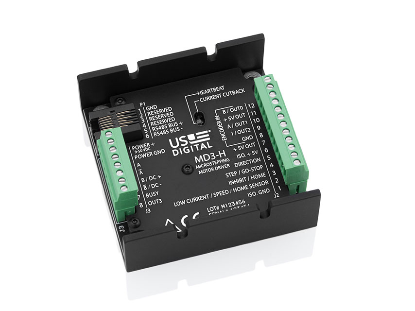
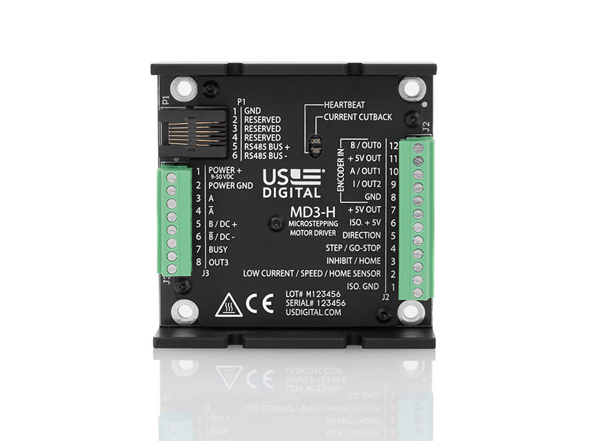
Unlike the MD2S, which uses jumpers and DIP switches for configuration, all configuration of the MD3 drive occurs over an RS485 serial port on P1. A USB to RS485 adapter (not included) is needed to connect a PC to the MD3. The serial port uses the Modbus RTU protocol. Modbus RTU is a simple, register-based command/response protocol. All MD3 settings such as phase current, microstepping, etc. are stored in thirty-two flash memory registers in the MD3. The MD3 User Guide gives full details on register read and write commands needed to configure the product. In addition to configuration, the serial port can also be used to send motion commands such as Move, Jog, Home, etc. so a host such as a PLC can control the MD3.
The default register settings are listed in the MD3 User Guide. The default serial communication settings are: Modbus device address = 1, 9600 bps, 1 start bit, 8 data bits, even parity, 1 stop bit. The default stepper motor settings are 1A current and 1/8 microstep.
US Digital provides the free MD3 Setup and MD3 Demo programs that provide a graphical user interface to the internal registers. The MD3 Setup program presents a simple interface for customers that want to configure the MD3 to function as US Digital’s existing MD2S-D or MD2S-P product. This program only allows the user to set options available on the MD2S-D or MD2S-P. The MD3 Demo program gives the user full control of all the features of the MD3.
