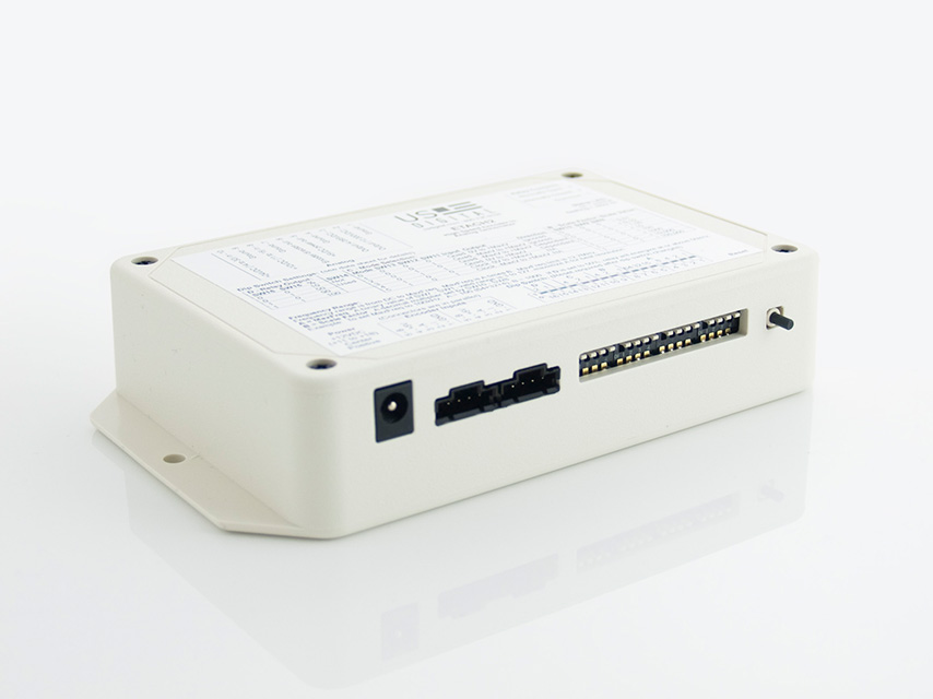
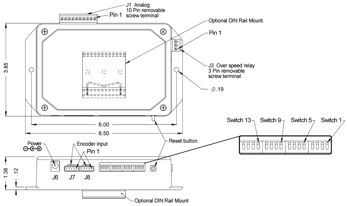
DIP switches 1 through 7 set the base frequency range in Hz or quadrature cycles per second as a binary representation of the switches. DIP switches 8, 9 and 10 provide a decimal scaling factor to the value of switches 1 and 7.
The frequency of the encoder output signal that is required to reach the full scale voltage of the ETACH2 is determined by the following equation. Please note: 1 = Up Position = Switch Off, 0 = Down Position = Switch On.
BF * SF = Encoder Frequency.
BF (Base Frequency) is determined by setting switches SW1 though SW7 (see table 1 in DIP Switch Definitions). The sum of the values assigned to the switches should be between 3 and 127. To maximize the resolution of the ETACH2 choose the largest possible value of BF that will satisfy your configuration operating requirements.
SF (Scale Factor) is determined by setting switches SW8 though SW10. Scale factors can be selected with ranges from 0.01 to 100,000 (see table 2 in DIP Switch Definitions).
Example 1: Encoder Frequency = 100kHz
Set BF to 100 (100 = 64 + 32 + 4; switches 7, 6 and 3 should be set to 1). Set SF to 1000 (SW10=1, SW9=0 and SW8=1).
BF * SF = Encoder Frequency
100 * 1000 = 100 KHz.
Example 2: Encoder Frequency = 200 kHz
Set BF to 20 (20 = 16 + 4; switches 5, 3 should be set to 1). Set SF to 10000 (SW10=1, SW9=1 and SW8=0).
BF * SF = Encoder Frequency
20 * 10000 = 200 kHz
