
Encoder Basics for Motion Control Engineers
Encoders are critical elements in a motion system because they provide position and/or velocity feedback to the motion controller, enabling the controller to close the control loop. The number of applications that require encoders is extensive and the types and sizes of encoders that serve these applications are just as numerous. It can be quite daunting for the design engineer to choose just the right encoder for his or her needs. This paper looks at the differences between encoder types and some of the options that can be specified to select the best encoder for the job, focusing on the most common encoder type: the rotary encoder.
Linear vs. Rotary Encoders
 Position/velocity encoders come in two mechanical configurations: linear or rotary. As the name suggests, a linear encoder measures the position or velocity of an object moving in a straight line. Typical linear applications are the control of linear motors or X-Y tables such as those found on vertical CNC mills or pick and place machines used in electronics assembly. They are also commonly found in devices such as metrology instruments including digital calipers. A rotary encoder, on the other hand, is used to measure angle or velocity of rotation of an object. Some typical uses include motor speed control, or the angular control of a movable PV array for solar tracking, or controlling the angular position of a robot arm.
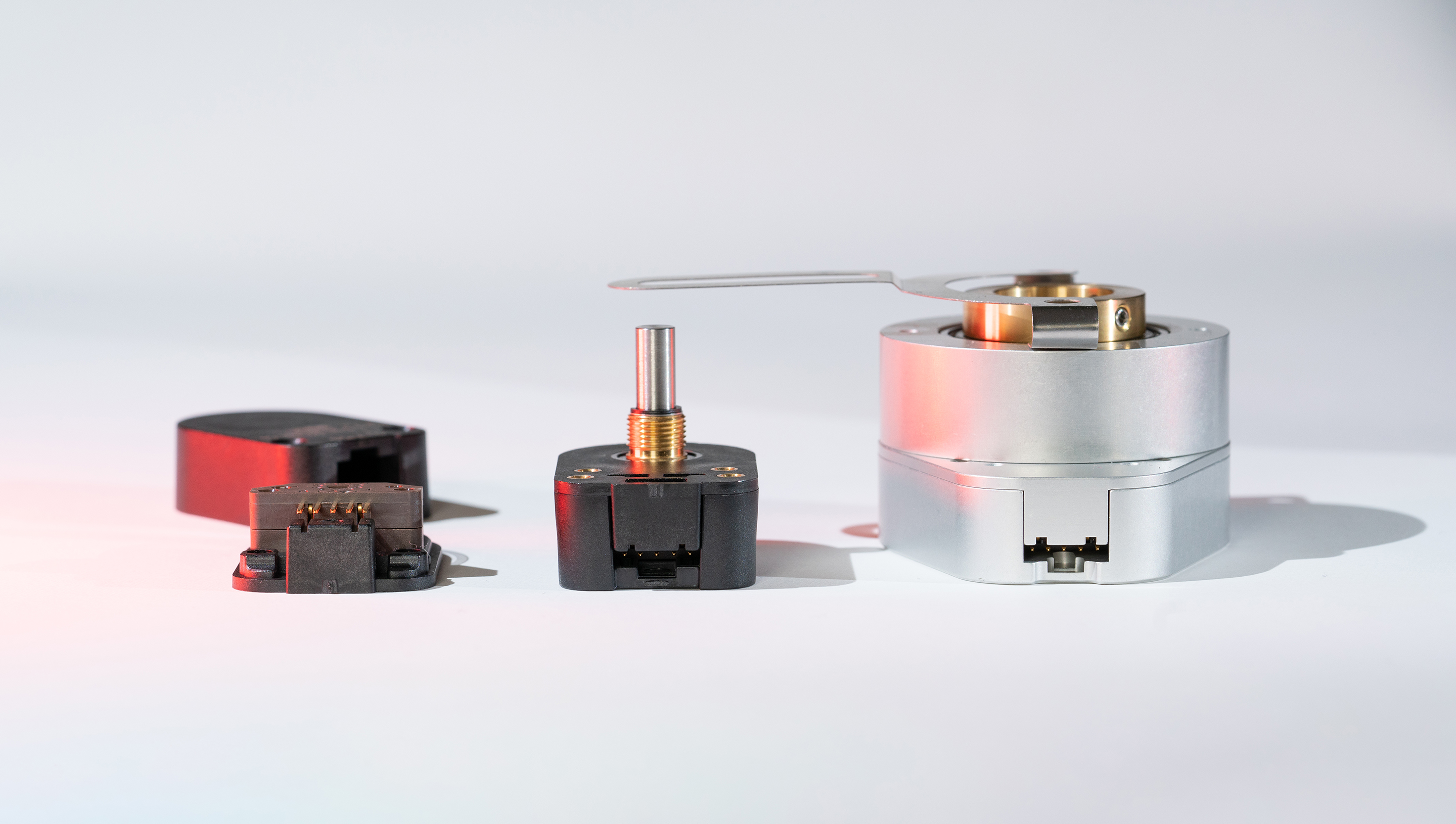
Rotary encoders are available with different physical specifications to serve different working environments.
For example, those used in harsh industrial applications must be designed to withstand rugged and extreme working conditions. Extreme temperatures, vibration, dirt and debris are some of the challenges that these encoders have to survive on a daily basis. As a result, industrial encoders tend to be big and solidly built to withstand the tough environment. For less harsh environments, such as those in electronics manufacturing, the emphasis may be on smaller size, lower cost or the ability to take advantage of more configuration options.
Optical vs. Magnetic Encoders
 Optical encoders are more common and provide the highest levels of accuracy and resolution. Rotary encoders use an optical sensor to detect light that is transmitted through or reflected from a disk (also known as a code wheel) whose pattern has both transparent and non- transparent lines. When the light is received by the sensor, the encoder puts out a high signal. Conversely, when the light is blocked by a line on the code wheel, the sensor puts out a low signal. So with a known pattern on the disk, the distance moved and speed of movement can be obtained using the signal information.
Linear and rotary encoders may use either optics or magnetics to sense movement.
Magnetic encoders use code wheels with alternating magnetic poles distributed around the wheel according to the resolution required. A magnetic sensor in the encoder detects the change in the magnetic field as the wheel rotates and produces a digital pulse train. Magnetic encoders have an advantage in that they are not as environmentally sensitive as optical encoders, and can be used in areas that have higher humidity, dust, and vibration. Magnetic encoders may also operate in various fluid environments. Magnetic encoders use less power than their optical counterparts, but typically do not provide the same resolution or positional accuracy as optical encoders due to inherent non-linearities in the magnetic field.
Use of a magnetic encoder may be preferable to an optical encoder when there is a chance for an optical disk to become “fogged” as moisture condenses on the code wheel. Consider an application where an optical encoder is held at a very low temperature and then the ambient temperature quickly increases. This quick temperature change can cause condensation on all surfaces of the encoder, including the optical code wheel. When the code wheel surface collects droplets of moisture, the light transfer of the code wheel image to the optical sensor becomes disrupted and a false or missing signal may occur on the output. With a magnetic encoder design, condensation of moisture is not an issue with the rotating magnet and magnetic sensor.
Mechanical Configurations
 Motor feedback encoders may contain their own bearings, or they may use an existing bearing set such as that found on the tail shaft of a servo motor. Which configuration option to use is a function of the stability of the shaft/bearings to which the encoder is attached. Feedback encoders with bearings are typically used when the application shaft has a significant amount of axial or radial run out (eccentricity or vibration). This style of encoder will incorporate some sort of flexible member, either a flexible shaft coupling or flexible body mount, to allow mechanical compliance with the application shaft operating irregularities.
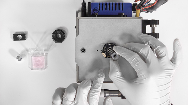
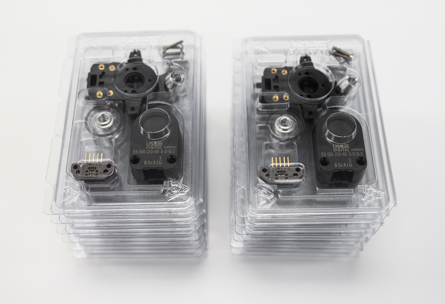 Modular encoders, also referred to as kit encoders, don’t contain their own internal shaft. They are assembled from components supplied by the encoder manufacturer and are designed to be attached to the tail shaft and end bell of the motor. These encoders rely on a mechanically stable motor shaft, as the shaft is responsible for holding the encoder’s internal rotating code wheel in a precise location relative to the encoder’s sensing element. For these applications, motor manufacturers put a considerable amount of effort in designing high-performance motors with very stable shaft/ bearing assemblies. Because the modular design does not add the expense of the extra set of bearings that a motor feedback encoder does, modular encoders offer the most cost effective feedback solutions.
Absolute vs. Incremental Sensing
One of the basic classifications used for encoders is whether their architecture is absolute or incremental in design. This refers to the type of output the encoder emits. As mentioned before, an incremental encoder uses the lines on the internal code wheel to output a digital pulse train that corresponds to the sensor detecting light and dark regions (or magnetic poles as is the case with magnetic encoders). Typically incremental optical sensors use multiple sensing elements separated by a certain number of degrees and simple analog to digital electronics to produce two phase-shifted output pulse trains (commonly referred to as channel A and channel B). The speed of rotation can be deduced from the frequency of the pulses, while direction of rotation is derived from the phase difference between the A and B pulse trains. In some incremental encoders, an additional optical channel is added to the code wheel, with a specific optical pattern and its own sensor designed to provide a once-per-rotation electrical pulse. This pulse, called an index, can enable the motion controller to calculate the angular position of the motor axis during the rotation of the encoder code wheel.
Incremental encoders are very useful for both position and speed control, as the pulses are very simple to process. The drawback to incremental encoders is that anytime power is lost, the true position of the mechanical system will be lost as well. In such cases the mechanical system will need to be reset to known initial location and restarted.
Absolute encoder outputs can take different forms depending on the encoder selected.
In some applications, this type of recalibration process is not possible, or is very expensive. An example would be semiconductor manufacturing equipment, where machines are required to maintain very tight positional tolerances. After a power loss event, the machines require the ability to continue an operation from the exact point at the moment power was lost, without performing a recalibration procedure. In such situations, absolute encoders are necessary.
An absolute rotary encoder differs from an incremental encoder in that it provides an output that corresponds to a specific angle of shaft position. That angle is specified to a resolution defined by a number of bits (e.g., 10 bits or 12 bits), depending on the total number of angular markings on the internal wheel. This is in contrast to the series of pulses emitted from an incremental encoder that must be counted to define a shaft’s position following a homing cycle.
Absolute encoder outputs can take different forms depending on the encoder selected. With some encoders, the shaft angle is converted to an analog voltage that increases monotonically as the shaft rotates. Absolute encoders may also provide a pulse-width modulated output that produces pulses that grow in width as the shaft is rotated. And some encoders provide angular information digitally via an RS-485-style serial interface supporting a standard communications protocol such as Modbus, CANOpen or Profibus. This makes it easy for a motion controller with one of these interfaces to determine the exact position of the shaft.
A multi-turn absolute encoder is a variant that has the ability to give absolute positional information over multiple turns of the shaft. The total available resolution of a multi-turn absolute encoder is the sum of the number of single turn bits plus the turns counting bits. For instance, an absolute encoder with a resolution of 10 bits per turn (dividing the 360 degrees around the wheel into 1024 segments) and providing a 12-bit turn count will yield 22 total bits of resolution (i.e., up to 1024 different angular position readings) over 4096 turns of the shaft.
With all the options available, the design engineer will have to choose the encoder that is best for the application. As a result of the added complexities, absolute encoders are more expensive than incremental encoders, but they are also much better suited for critical positional control situations.
Accuracy vs. Resolution
As discussed, encoders provide the motion controller with information about the velocity and/or position of a rotating shaft or linear motion actuator. The encoder provides position information plus or minus a specific tolerance which characterizes the accuracy of the device. The accuracy specification is the most commonly misunderstood aspect of an encoder. Often an encoder with higher resolution is specified on the assumption that more lines on a disk will provide more positional accuracy. This is incorrect, as accuracy and resolution of an encoder are not connected in any way.
The accuracy of an encoder is primarily defined by the precision with which the code information is placed on the disk and how concentric the disk pattern rotates with respect to the encoder’s sensing element. Encoder accuracy is specified in units of arc-minutes or arc- seconds. For example: a low resolution incremental encoder of 100 lines (or magnetic poles) per revolution will report 180 degrees just as accurately as an encoder with 10,000 lines per revolution if they both share the same positional accuracy specification. The high resolution encoder can just break the steps between 0 and 180 degrees into finer increments.
Another way to understand the difference between accuracy and resolution is to think of encoders as a form of analog to digital converter. They convert the analog value of mechanical shaft position to a digital form. As with their electronic A to D cousins, it isn’t enough to simply specify resolution. The accuracy of a traditional electronic A to D is usually specified with two terms: integral non-linearity, and differential non-linearity.
Differential non-linearity is the amount by which adjacent codes differ from each other and is directly tied to resolution; it has to be less than one bit, or else the resolution has been over-specified (a 12 bit encoder with a differential non- linearity of 2 bits is really an 11 bit encoder). With encoders, differential non-linearity corresponds to the monotonicity of the encoder output codes. For an incremental encoder this is almost never a problem: if the encoder has 1000 lines on the disk you will get 1000 pulses out of the encoder.
Integral non-linearity is a measure of how much the actual response of the converter departs from the ideal response of a perfect converter; most electronic A to Ds have a bow-shaped error curve relative to a line drawn from zero to maximum input value. However, integral non- linearity is more elusive and difficult to pin down in the world of encoders. It won’t be found on most data sheets, though it still exists, usually as a sine wave shaped error curve.
The major cause of integral non-linearity in encoders is the concentricity error between the code wheel and encoder sensing element. There often is a set screw that secures the code wheel hub to the shaft. This, combined with the clearance necessary to slip the hub onto the shaft, gives rise to a very slight eccentricity of motion relative to the encoder’s disk pattern detection system. When the amount of eccentricity is known, the nonlinearity can be calculated and compensated for in the motion control algorithm.
Conclusion
Encoders are available in many mechanical and functional versions. Understanding some of the basic tradeoffs in encoder design will allow a system designer to properly select an encoder that will meet his/her cost and performance needs over the life of their application.
ABOUT US DIGITAL
With over a million off-the-shelf configurations, plus any number of custom product offerings, US Digital has delivered quality in motion since 1980. US Digital offers stellar service, delivering motion control solutions best suited to each unique need. Automated systems, continuous improvement protocols and stringent testing ensures we bring quality to every product manufactured.
Located in Vancouver, Washington, our vertically integrated facility and personalized service provides customers with industry lead times significantly shorter than the competition, offering same-day fulfillment on most orders.
ENCODER BASICS FOR MOTION CONTROL ENGINEERS
Would you prefer to print this white paper or save it for later?